Category Archives: Fanuc Turn

Setting the Workshift (Fanuc CNC Lathe)

Category : Beginners Fanuc Turn

Setting the Workshift

workshift

This article is about the Workshift on a CNC Lathe with a Fanuc control.

As a beginner one of the first things you will need to learn is how to set the workshift.

The workshift is an adjustable figure that tells the control where the work zero is.

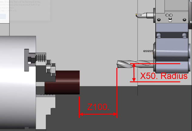
It defines the relationship between the turret and the workpiece.

Workshift

So we have a programme for our part on a our CNC Lathe. Let’s assume this programme is perfect with no errors.

But at the moment it’s just a part floating around in space.

Workshift

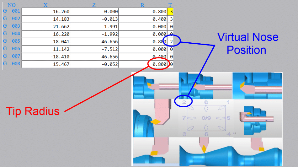
You have measured the tools using cut and measure or a tool presetting arm. You also need to tell the machine the radius of the cutting tool tip and its virtual nose position.

Workshift
Tool tip radius and virtual nose

So now all the machine needs to know is where the workpiece stock is. That’s where the workshift comes in.

WorkshiftTool Presetting Arm

The setting of the workshift will vary from one machine to the next but just think about this logically.

1 You have a program.

2 Your machine knows where your tools are in the X and the Z axis.

So now your machine needs to know where the workpiece is in order to complete the jigsaw puzzle.

To do this we need to set the workshift.

With regards to the X axis this never changes because the centreline of the machine is always the same.

Just Worry About Z

Sooooo this is just about Z.

The way we do this is to effectively tell the machine where the tools are in relation to the workpiece.

First you need to call out a tool and its offset.

T0101 (Call tool one and offset one)

You could do this in MDI

Workshift
Fanuc MDI Screen calling tool one and offset one

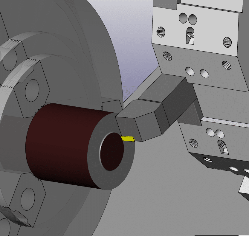
Bring the tool to the front face of the component. If you want to machine metal from the front face then you would position the tool slightly behind the front face.

You could even start the spindle and machine the front face. That way you will know you took off the right amount of metal.

Workshift
Machine the front face when setting workshift

(You can use any tool for this provided it has been measured and you call its offset)

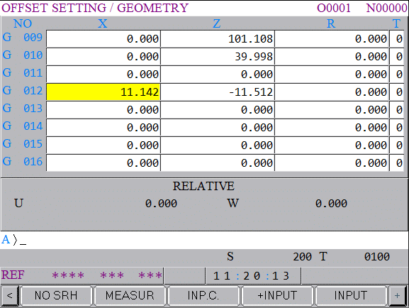
Cursor to the Z underneath (MEASUREMENT) on your workshift screen.

Workshift

Type in 0 then press INPUT


The Z SHIFT VALUE will change.

If you want to you can input zero into shift value on the left to reset it before you start.

I like to do this when I am setting the workshift because you can clearly see the new figure when it goes in.

My screenshots are from newer Fanuc controls. Even if yours is an old banger it will be much the same.

New CNC Machines

Be very careful not to set anything in the X figures because it will completely mess up your X axis position. This could leave you in deep shit.

It is always good to note the X figure even if it is set to zero.

Workshift

This X figure can be used to set the centre-line for your drills and centre cutting tools so it may not be zero.

Mine is set to X270. which is the centreline of my machine. So if I am using a drill or any tool that works on centreline then I only need put zero in the X offset.

Be careful before changing this if you have a tool measurement arm as it will alter all your X figures. You will need to re measure all of your tools.

In the table above tool 9 is a drill and because my workshift is set to the centreline (X270.) I would input zero in the X offset geometry.

Otherwise you would have a standard figure that you put into X for all your centreline tools.

On my machine it would be 270. but it usually ends up at something close like X270.106 which is hard to remember.

I often see this figure written on the side of the machine in felt tip pen for operators to remember.

If you do have a figure in the X it is really important not to change it. I would recommend using G10 in all your programmes. That way you can always be sure this figure is correct.

(G10 is a way of entering your offsets and workshift from the CNC Program)

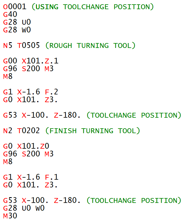
In the program above it is the G10 P0 X270. line. The P0 tells the control to write to the workshift.

This way even if you fuck up the X position the control will just ignore you and keep writing the correct figure in at the beginning of the program.

Please note I am not putting anything in the Z for the G10 as I don’t want this updating. You can do this if you want, but you need to remember that you can now only alter the Z from the G10.

Testing The Workshift

Once your workshift is set you are ready to prove out your part.

You can test the workshift in MDI if you wish.

T0101;
G0 Z0;

Make sure to override the rapid moves (not 100%) and look at

DISTANCE TO GO

If when you run your program the front face of your part does not clean up or you feel you are taking too much off then the workshift will need to be altered.

Note

Changing the workshift moves all the tools together. I does not change the relationship between the tools.

How to Alter The Workshift

Workshift

Always use + INPUT as this will add the value to the present value.

If you use input it will replace the figure and now your in trouble.

How to Adjust workshift

Be Careful Not to Alter X

Thanks for watching and reading

If you have been affected by any of the issues in this post or need CNC Counselling then contact me.

Or call us

If you want to learn to program CNC Milling Machines

Look no further Contact CNC Training Centre

Siemens Sinumerik Training


Using U To Program Taper CNC Lathe

Category : Fanuc Turn Haas Turn

I recently wrote an article on the use of incremental U and W on a CNC Lathe for incremental programming.

I must be honest I didn’t have that many creative uses for it.

Anyway when I posted it on Linkedin I did get some interesting replies and comments. I was surprised to see how many people do use incremental U and W.

incremental U


About a year ago I was working at Gardner Aerospace and we were struggling to get rid of a taper on a shaft we were machining.

Not a particularly difficult job other than this pesky taper we kept getting.

It was something like 30mm diameter by about 140mm long. We were making it on a new Haas ST lathe we struggled to hold the size which was about plus or minus .02mm and were getting a taper too.

I noticed that when we programmed a taper it was easy to make a mistake.

incremental U

The above program would take the size .015 less.

incremental U

When it came to changing the taper again the calculation had to be made. I suddenly had a brainwave and realised we could program it in incremental by using a U figure.

incremental U

The great thing about doing this is that you can see exactly what taper you have and it’s really easy to modify. 

The other thing is that the figure is always going to be small so it’s easy to spot mistakes.

I got so excited I even made a video.

Thanks for watching and reading

If you have been affected by any of the issues in this post or need CNC Counselling then contact me.

Or call us

If you want to learn to program CNC Milling Machines

Look no further Contact CNC Training Centre


G74 Drilling Cycle With G96

Tags :

Category : Fanuc Turn Mazak Turn

G74 Drilling Cycle With G96

G74 Drilling Cycle with G96.

On a CNC lathe G96 is used for most machining. It was amazing in the old days when we suddenly discovered G96.

Because you are using a constant surface speed the metal cutting is consistent so you get a great finish.

The Black Art Of CNC Programming

CNC Programming was a bit of a black art back in the old days and generally speaking we used G96 for everything except for screw cutting and drilling holes on centreline (G74 Drilling Cycle).

When CNC Programming a drilled hole you would always use G97, (this means the speed is in RPM).

If you were to program for example G96 S50 M3 and then rapid to X0 and Z3. ready to drill a hole the machine would just go to its maximum RPM. This would be the speed you set in your G50. (The G code used to restrict the speed.)

Oh by the way that 50 meters per minute is for a B & Q drill.

Don’t get me wrong I love B & Q products but HSS drills are not for grown up engineers they are great for metal work classes at school and making a coffee table for the misses but it’s time to join the big boys and spend some money.

I Digress

Anyway the machine would calculate the speed at its current diameter. So at zero the spindle would always be flat out.

So you could say G96 is pretty useless for a drill.

But you would be wrong!!!!!!

Take a look at this bit of code.

G74 Drilling Cycle

The idea is to send the machine to the drill diameter. Because the machine is in G96 it calculates the correct speed. When you then issue G97 it fixes the speed. Now when you move to X0 it has the correct speed.

Let The Machine Do What It’s Good At

Mmmmmmm… So all you need to do is send the drill to its diameter and the machine does the arithmetic.

Let the machine do what it’s good at and you do what you’re good at.

What are you good at by the way?

Threading is the same if you were machining an M20 thread at 100m/min calculate the surface speed.

(This is the quickest way I have seen)

20/314.2 =.06365

100/.06365 = 1571 RPM

You could do the same thing let the machine do it’s shit.

Rapid to the diameter of the thread then program G96

G0 X20. Z5.;
G96 S100 M3 (Start Spindle at 100 metres per min);
;
G97 (This will swap to RPM and clamp the speed at the correct RPM);
X21.;
;
G76 P010060 Q20 R.02;
G76 X16.93 Z-25. P1534 Q485 F2.5;
;

ETC

So with this bit of code you can get the machine to calculate your speed.

Thanks for watching and reading

If you have been affected by any of the issues in this post or need CNC Counselling then contact me.

Or call us

If you want to learn to program CNC Milling Machines

Look no further Contact CNC Training Centre


G94 Facing Example (Sample Program)

G94 Facing Example

G94 Facing Program Example

G94 Facing Example

:Blank Size: 65mm Diameter 85mm Long

:Final Size: 65mm Diameter 82mm Long

This program will rapid to X66. Z3. it will then machine the face down to Z0 in three cuts. The first G94 line tells it to face past centreline to X-1.6 at a feed-rate of F.2 The Z axis moves to Z2.

Cuts
1: Z2.
2: Z1.
3: Z0

The cycle stays in the control until cancelled by a G0 rapid command.

So it remembers exactly what you told it, a bit like my wife, she keeps reminding me of the time I got so hammered I pissed in her wardrobe (some of the shoes still smell to this day).

The G0 G28 U0 W0 will move the turret back to machine reference point.

The G0 will cancel the G94 Facing cycle.

G94 Facing Example Is It Any Good?

Well personally I think it is.

Now I’ll tell you why. You could say it’s really easy to write the program to face a part.

G0 X50. Z0
G1 X-1.6 F.2
G0 X50. Z2.

So that’s easy to do but….

Some one wrote a comment on one of my posts the other day and he started it by saying “back in the real world”.

Can’t lie and say it didn’t piss me off but being the mature well balanced man that I am I ignored it.

Now my inner nasty, immature, unbalanced me said “look mate I was in the real world when you were still shitting yellow”. Obviously I didn’t post it and if your reading this now thinking it’s you, well it isn’t.

Anyway as to the G94 Facing Example

In the “real world” you get to the end of the batch of parts and find that one of them is way too long and you need to face a shit load off the front.

Now had you used the cycle as below and got into the habit of always using it.

G0 X50. Z3.
G94 X-1.6 Z0 F.2
G0 G28 U0 W0

The alteration would be really easy.

G0 X50. Z12. (Imagine You Have An Extra 12mm On the Face)
G94 X-1.6 Z10.5 F.2
Z9.
Z7.5
Z6.
Z4.5
Z3.
Z1.5
Z0
G0 G28 U0 W0

Rapid Move Cancels G94

Note don’t forget you must have the G0 rapid move at the end to cancel the G94.

(Just like G0 cancels a canned cycle in milling)

Don’t be tempted to put G0 in the moves as the control will just wiz around in Z and sit there laughing at you.

G0 X50. Z12. (This is what not to do)
G94 X-1.6 F.2
G0 Z10.5 (NO NO NO NO NO NO)
Z9.
Z7.5
Z6.
Z4.5
Z3.
Z1.5
Z0
G0 G28 U0 W0

See full explanation

Using G94 on a Haas Lathe

Thanks

If you have been affected by any of the issues in this post or need CNC Counselling then contact me.

If you want to learn to program CNC Milling Machines

Look no further Contact CNC Training Centre


How G28 Works. Why two pushes of CYCLE START?

How G28 Works

Every wondered why G28 takes two presses of the CYCLE START Button when you are in single block.

How G28 Works

Be amazed you are about to find out.

One of my pet hates, and at my age you have thousands, is when people say

“Oh I don’t know we’ve always done it”

I just think, well you are stood at this machine for eight hours a day why not find out what’s going on.

How G28 Works

How G28 Works

G28 tells the machine to return to its home position. This is usually a convenient point for a tool change.

The command on a machining centre looks a bit strange.

G28 G91 X0 Y0 Z0

Why G91?

Well G28 means return to your home position via an intermediate point.

So if you programmed G28 X0 Y0 Z0 then your machine would rapid down to the workpiece (probably crash) and then go to it’s home position.

What G28 G91 X0 Y0 Z0 tells the machine is this……

  • The reference point is incrementally zero from where you are.
  • So the machine does not move.
  • Then it goes to it’s home position.
  • Hence the two presses of cycle start.

On a CNC Lathe we use U and W for incremental. Read this post if you don’t know.

So if you programmed G28 U0 W0 your X and Z axis would return to their home position. This being because the reference point is incremental.

If you programmed G28 X0 Z0 you would probably get a collision like below.

Well at least it went home.

First move is to X0 Z0 which is the front of the part. (This is your reference point.)

The machine would then move back to zero return.

G28 is fine on a CNC Lathe but on a CNC Machining Centre you must remember to change back to G90 (Absolute).

My preference is to use G53 to get back to your home position.

Read this article if you never heard of G53.

Please note some older machines don’t have G53. Oh and it is classed as an option!

If you are affected by any of the issues raised in this post or need CNC Training then contact us.

Contact CNC Training Centre

Don’t forget to watch my Tutorial Videos

We offer training on all types of CNC Machines and controls check em out.

Or fill out the contact form below


Careers in CNC

View all current vacancies in CNC

Click here

Call David: 07834 858 407