This article is about CNC turning programs and the use of T00 or T0000 to cancel the tool offset.
My daughter is autistic, and one of the things that she has taken great delight in doing during the Covid lock down, was picking up on the stupid nonsensical phrases and expressions that neurotypicals have created in their non-binary brains.
In case you don’t already know neurotypical is an expression used by autistic people to describe non-autistic people. I still haven’t worked out if it is a term of endearment or mildly offensive but I don’t really care anyway.
Anyway, whilst I was writing an article about using multiple offsets, yet to be completed, I suddenly realised why it is a good idea to cancel the tool offset on a CNC Lathe (more about that later).
We were sat drinking tea in our summer house, me my wife and my daughter.
I know it sounds grand but really, it’s not exactly a summer-house it’s more of an old shed. It’s one I converted to compete with my neighbours when they had a fancy new summer house built.
Just a few finishing touches needed
I was talking about this article in rather abstract terms as my wife and daughter are none engineers but always pretend to be interested in my rantings.
Anyway, with reference to tool offset cancellation I said “you learn something new every day”.
My daughter immediately retorted “oh so what did you learn yesterday?”. Fortunately, I could think of something I remembered learning that there are 206 bones in the human body, so I used it.
I need to add a this point that my daughter is not an autistic savant and we still need google and takeaway menus. She’s not like that bloke in “Rain Man” who can remember every number in a fuckin’ phonebook.
The expression is “if you know one autistic person, you know one autistic person”
Anyway with her autistic brain I should have known this wouldn’t suffice. “The world tilts at 23.5 degrees on its axis” I quickly added.
“You already knew that” she said.
(Please ignore this if you think the world is flat as I know a lot of my readers do)
She insisted that I should go back at least three weeks in order to prove the validity of the statement.
I decided to give in and the conversation ended by me admitting that all neurotypical people are stupid.
In our household that’s a result and a common strategy we use to resolve this kind of conflict.
Such idioms as “washing your dirty laundry in public” are just banned unless you think you have a simple way of explaining it.
A friend once exclaimed that “there is more than one way to skin a cat!” and as a result required a police escort to get home (joke).
My daughter has a cat and her whole existence revolves around it. I’ll let you imagine her reaction.
Using T00 to Cancel tool Offsets
Anyway, this was going to be an article about using multiple offsets in a CNC Turning program.
They are a bit like multiple orgasms but not nearly as much fun. Anyway I had this eureka moment with regards to T00 and ditched the whole thing.
On a CNC Lathe we use a four-digit number when we do a tool change.
T0101 for example.
The first two digits make the turret index T0101 (index to tool 1)
The second two T0101 will call an offset. You will note I said an offset because it can be any.
By the way some controls like Haas omit the first zero on a tool change.
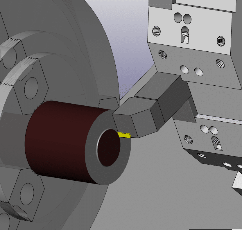
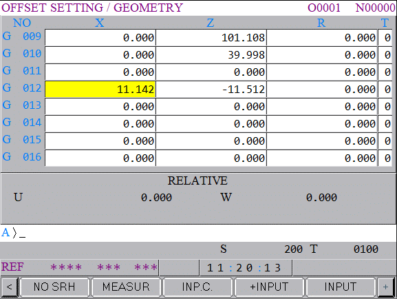
Geometry offset page on a Fanuc CNC Lathe
In the above case it’s offset 1 but it could be T0112 this would index to tool 1 and use offset 12.
Geometry offset page on a Fanuc CNC Lathe
Anyway thinking about these four digit numbers made me think about when you use zeros.
On older machines you used to have to cancel the offset by stating T0100 or much safer T0000. Otherwise the machine would add the new offset to the old one and a shitstorm would ensue.
I had consigned, this now inert procedure, to the CNC Turning equivalent of room 101 or at least the annals of CNC History. Anyhow, it seems there is life in the old T000 dog yet.
I love this puppy I’m going to use it in every post from now on
Now this is where that eureka moment happened in my summer house / luxury shed and I wrongly claimed to learn something new every day.
The Theory
When you write a CNC Turning program you can either return the tool back to the machine reference or return it to a tool change position.
Now the first option (reference) is OK if it is a small a machine. In other words it’s not gonna take it a week to get there.
On a big machine you would have to navigate around all sorts of shit like the tailstock or a steady or the boss’s Bentley. And it would almost definitely be a waste of time.
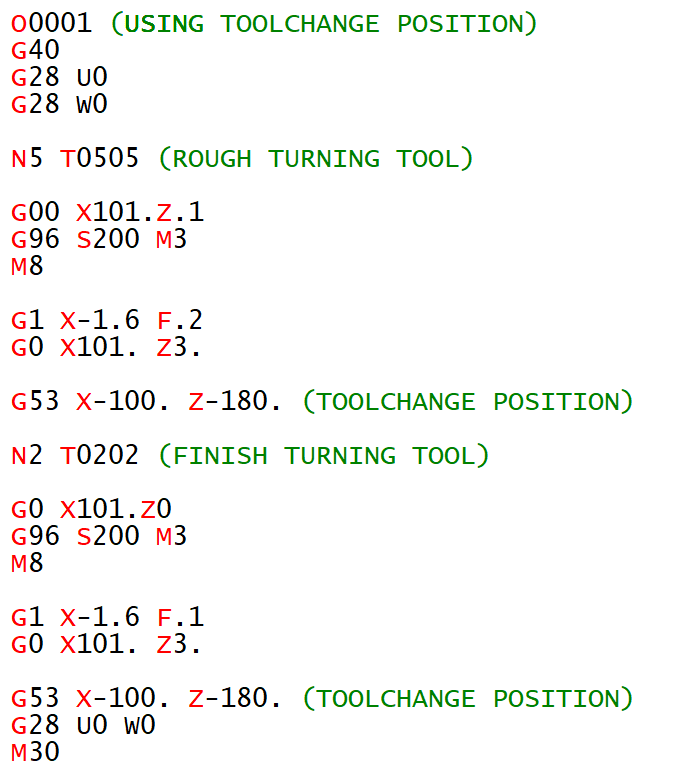
Soooo normally we would use a tool change position. This would be making use of G53
Using G53 for tool change position
CNC Turning G53
Because the G53 uses the machine coordinate system it will be the same place for each tool.
You could then put this position in a sub program. That way it would be the same for every tool. If you needed to change the position you would only need to change it once in the sub-program.
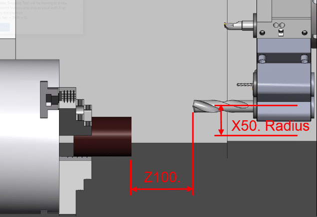
I will forgive beginners for thinking you could just rapid each tool to the same position away from the work piece.
For example G0 X100. Z100. for every tool.
Sending a drill to a positionSending a turning tool to a position
Just look at the turret position in the pictures above. Although the X Z position of both tools is the same there is a huge difference in the turret position.
This could work but when you pick the program up again maybe months later. The tools could be different lengths the tool-change position would have to be altered.
Your drills may not be the same length and the machine may even over-travel when you try to move it to your old tool change position..
Using a G53 you can always allow for the longest tool and know your index position is safe.
Remember G53 does not consider the tool offset or the work offset. To be honest G53 is the selfish bastard of the G codes it just does not give a flying shit what offset is active.
Eureka
Anyway, thinking about cancelling tool offsets it gave me an idea.
If at the end of each CNC Turning tool you cancel its offset. you could send it to a known position.
Because no tool offset is active this would always be the same place.
Some of you probably already do this but honestly, I never thought of it.
I intend to program this way from now on.
Using T00 for your tool change position
You should be able to use T00 or T000 to cancel your tool offset.
Don’t Do This (I really shouldn’t be telling you)
You can use the tool number plus the zeros so to cancel T0101 you could put T0100. I strongly recommend that you do not do this because it introduces an index move and therefore another potential collision.
You would need to remember to change this on all tools if for some reason you moved the tools around in the turret.
Oh yea about the multiple offsets. I will be writing and article on it when I can be arsed but in the meantime here is a video.
Thanks for reading my articles (no flies were killed in the writing of this article) except for the little bastard that’s flying around my office.
I always begin my training sessions by telling my students not to remember anything I say.
This sounds completely stupid and my excuse is it wasn’t my idea to say it.
About ten years ago I worked in France. After about a year it seemed obvious that I would need to speak to people to order “Fish n Chips” and stuff like that.
Anyway I got these CD’s to teach me French and the bloke (can’t remember his name) started off by telling you not to remember anything he told you.
Reverse Psychology
I think there is a bit of reverse psychology going on but the main idea is that you understand not remember. It didn’t work for me because I still managed to completely fuck up the language.
Not realising French Canadians speak differently to native Frenchmen (I was working for Bombardier) . Anyway I asked this bloke, in French, to “will you come with me”. I can’t remember what it is in French and after all the bloke on the CD had specifically told me not to remember.
Anyway turns out this had a sexual connotation and made me the complete laughing stock everywhere I went from then on. (I’ll let you do the maths on that one.)
“OK which one of you bastards bought all the fuckin toilet paper in lock-down?”
Now I know what you are thinking, “that is the gnats cock of CNC Turning G Code Lists”. Honestly size isn’t everything.
Learn these first and just by seeing them every day they will just sink into your brain.
When it comes to CNC Programming it is important to enjoy your self and not get bogged down trying to remember loads of G Codes.
The truth is you only need to remember a few and it’s all about understanding what they do.
For Example This is in your Programme.
You watch in amazement as it cuts your part.
So you look up what G71 means on your list of G Codes printed in large letters on the side of your machine.
This article is about using G10 on a CNC Lathe to set the work shift or work zero offset as it is known on a Haas control.
If you have ever used Mazak machines you will know that when you call a program the work offset is kept with it.
Obvious really……
I mean if you were teaching your dog or your cat to program a CNC Lathe and you told him that he had to reset the workshift every time he called a new program what would he say.
I mean nothing really but he’d probably give you a strange look.
But you can do it on a Fanuc control or on a Haas control.
You just put this………………….
G10 P0 X0 Z-98.1
So you would put that at the head of your program and it would change the work shift screen as above.
Advantages
No need to set workshift everytime.
Automatically sets X figures so there’s no chance you could alter it by accident.
Well there is a slight catch.
It’s obvious really but from now on you can only change the workshift from the program.
If you altered it on the workshift screen it would just change back when you run the program.
Now I know your not stupid enough to do that but I bet the bloke on nights is.
This article is about the Workshift on a CNC Lathe with a Fanuc control.
As a beginner one of the first things you will need to learn is how to set the workshift.
The workshift is an adjustable figure that tells the control where the work zero is.
It defines the relationship between the turret and the workpiece.
So we have a programme for our part on a our CNC Lathe. Let’s assume this programme is perfect with no errors.
But at the moment it’s just a part floating around in space.
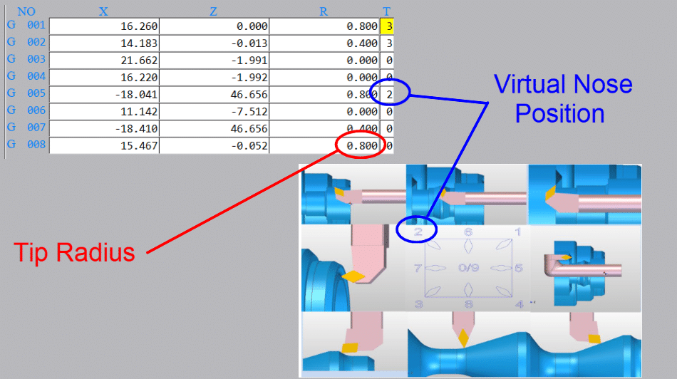
You have measured the tools using cut and measure or a tool presetting arm. You also need to tell the machine the radius of the cutting tool tip and its virtual nose position.
Tool tip radius and virtual nose
So now all the machine needs to know is where the workpiece stock is. That’s where the workshift comes in.
Bring the tool to the front face of the component. If you want to machine metal from the front face then you would position the tool slightly behind the front face.
You could even start the spindle and machine the front face. That way you will know you took off the right amount of metal.
Machine the front face when setting workshift
(You can use any tool for this provided it has been measured and you call its offset)
Cursor to the Z underneath (MEASUREMENT) on your workshift screen.
Type in 0 then press INPUT
The Z SHIFT VALUE will change.
If you want to you can input zero into shift value on the left to reset it before you start.
I like to do this when I am setting the workshift because you can clearly see the new figure when it goes in.
My screenshots are from newer Fanuc controls. Even if yours is an old banger it will be much the same.
Be very careful not to set anything in the X figures because it will completely mess up your X axis position. This could leave you in deep shit.
It is always good to note the X figure even if it is set to zero.
This X figure can be used to set the centre-line for your drills and centre cutting tools so it may not be zero.
Mine is set to X270. which is the centreline of my machine. So if I am using a drill or any tool that works on centreline then I only need put zero in the X offset.
Be careful before changing this if you have a tool measurement arm as it will alter all your X figures. You will need to re measure all of your tools.
In the table above tool 9 is a drill and because my workshift is set to the centreline (X270.) I would input zero in the X offset geometry.
Otherwise you would have a standard figure that you put into X for all your centreline tools.
On my machine it would be 270. but it usually ends up at something close like X270.106 which is hard to remember.
I often see this figure written on the side of the machine in felt tip pen for operators to remember.
If you do have a figure in the X it is really important not to change it. I would recommend using G10 in all your programmes. That way you can always be sure this figure is correct.
(G10 is a way of entering your offsets and workshift from the CNC Program)
In the program above it is the G10 P0 X270. line. The P0 tells the control to write to the workshift.
This way even if you fuck up the X position the control will just ignore you and keep writing the correct figure in at the beginning of the program.
Please note I am not putting anything in the Z for the G10 as I don’t want this updating. You can do this if you want, but you need to remember that you can now only alter the Z from the G10.
Testing The Workshift
Once your workshift is set you are ready to prove out your part.
You can test the workshift in MDI if you wish.
T0101; G0 Z0;
Make sure to override the rapid moves (not 100%) and look at
DISTANCE TO GO
If when you run your program the front face of your part does not clean up or you feel you are taking too much off then the workshift will need to be altered.
Note
Changing the workshift moves all the tools together. I does not change the relationship between the tools.
How to Alter The Workshift
Always use + INPUT as this will add the value to the present value.
If you use input it will replace the figure and now your in trouble.
How to Adjust workshift
Be Careful Not to Alter X
Thanks for watching and reading
If you have been affected by any of the issues in this post or need CNC Counselling then contact me.
Or call us
If you want to learn to program CNC Milling Machines


 Tool Presetting Arm