Month: May 2022

Surface Finish CNC Turning

Category : Beginners

CNC Turning Surface Finish

Ever wondered what feed rate is best to give you a particular CNC Turning surface finish? Or do you just guess?

Well look no further. From now on you’ll be able to work out what feed-rate will give you the surface finish you require when CNC Turning.

Oh and there’s a formula where you can work out what surface finish you’re going to achieve without a fortune teller.


We are going to use um Ra.

The um stands for microns.

The Ra stands for roughness average.

Here is a full explanation if you really want to know. 

CNC Turning


You can buy a flat block like the one above which you can use as a comparison to see what surface finish you’re getting.

The section above is for CNC Turning surface finishes.

So you can already see that 12.5 is like a plowed field and .4 is like a babies arse (as my father used to say) .

So if you’re fixing a fence post then 12.5 might be OK.

Surface Finish The Dreaded Formula

surface finish

First of all what feed rate would you need to obtain a certain CNC Turning surface finish.

CNC Turning

Now what if you’re already machining the part. That means you know the feed rate. What surface finish will you get?

CNC Turning

So………….

Our tip radius is .8mm

CNC Turning

We want to achieve a 3.2 um Ra  CNC Turning surface finish

CNC Turning

So here’s the formula.

CNC Turning

Let’s do this bit first.

https://www.youtube.com/watch?v=vWQgBtlUUMM&ab_channel=MotoMadness

8 x .8 x 3.2 = 20.48

Now let’s divide it by 1000

https://www.youtube.com/watch?v=vWQgBtlUUMM&ab_channel=MotoMadness

20.48 / 1000 = .02048

Now lets square root the answer.

https://www.youtube.com/watch?v=vWQgBtlUUMM&ab_channel=MotoMadness

Square root of .02048 = .143

So the feed-rate you need is F.143

CNC Turning

OK… You Came Back. You Ready to Carry On?

Anyway let’s see how you do it backwards.

surface finish

So imagine you had been turning these imaginary bits with a .8mm radius insert at a feed-rate of .143 (F.143)

First of all square the feed rate .143 x .143 = .020449

CNC Turning

Now do the bottom bit 8 x .8 = 6.4

surface finish

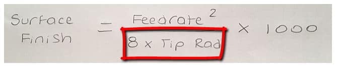
Now divide the top by the bottom.

surface finish

.020449 / 6.4 = 0.00319515625

Then simply multiply this by 1000

0.00319515625 x 1000 =3.19515625 (3.2)

That’s 3.2 to you

surface finish
A surface finish comparator

It worked backwards!!! Phew what a relief.

Surface Finish, Now Let’s Think About This

So to get a 3.2 finish with a .8 tip radius you would need a feed rate of .14

Now let’s do the same calculation with a .4 radius tip.

surface finish
Calculate surface finish

So did you work it out?

Here’s one I prepared earlier.

The answer is .101

And if you can be bothered to work it out with a 1.2 radius tip.

The answer is .175

.4    =  .101
.8    =  .143
1.2  =  .175

Interesting

So as the tip radius gets bigger you get to increase the feed rate!

Thanks for watching and reading

If you have been affected by any of the issues in this post or need CNC Counselling then contact me.

Oh yea we do CNC Training too not to mention Classroom Training.

Or call us

If you want to learn to program CNC Milling Machines

Look no further Contact CNC Training Centre


G82 Drilling Program Example

G82 Drilling Program Example

G82 Drilling Program Example, this simple part has four M12 holes drilled countersunk and tapped.

The datum is the centre of the part so the holes positions are.

X55. Y55.
X-55. Y55.
X-55. Y-55.
X55. Y-55.

G82 Drilling Program Example

Here is the CNC code

G82 Drilling Program Example

The machine first moves to X-55. Y-55. and rapids the Z axis to 3mm above the part.

It then rapids the Z axis down to 1mm above the part R1.

The G82 Cycle instructs it to drill a hole 6mm deep (Z-6.) at a feed of 200mm per minute (F200.)

When it gets to depth the P3000 tells it to dwell for 3000 milliseconds which is 3 seconds. No decimal point allowed. (Varies on controls)

When the hole is done it rapids back to the initial point (Z3.) This was in the line

This is because of the G98.

If it were G99 it would return to 1mm above the job (R1.)

See explanation of G98 and G99

Once the cycle is active each time it sees a position it repeats the drilling process.

When the G80 is programmed it no longer drills holes.

Now watch the video to see it all in action.

G82 Drilling Program Example

Haas G82 example

It’s been great fun writing this article for you but to be totally honest i think this cycle is a complete waste of time. Whenever I have put a dwell in a spot drilling cycle it always seems to chatter.

However if you do use this cycle please let me know if you have success with it.

Thanks

If you have been affected by any of the issues in this post or need CNC Counselling then contact me.

If you want to learn to program CNC Milling Machines

Look no further Contact CNC Training Centre


G83 Peck Drilling Program

Category : Beginners Fanuc

G83 Peck Drilling Program Example

G83 Peck Drilling Program, G83 is a deep hole peck drilling canned cycle.

Cycle G83 drills holes breaks up the chips as it goes. It fully retracts from the hole after each peck.

This simple part has four M12 holes drilled countersunk and tapped. The datum is the centre of the part so the holes positions are.

X55. Y55.
X-55. Y55.
X-55. Y-55.
X55. Y-55.

G83 Peck Drilling Program

G83 Peck Drilling Program

Here is the CNC code

G83 Peck Drilling Program

The machine first moves to X-55. Y-55. and rapids the Z axis to 3mm above the part.

G83 Peck Drilling Program

It then rapids the Z axis down to 1mm above the part R1.

The G83 Cycle instructs it to drill a hole 17.5mm deep (Z-17.5) at a feed of 200mm per minute (F200.) 

The Q2. tells the machine to drill the hole in 2mm steps. After each step it retracts to the surface of the part.

This allows all the chips or powder to come out of the hole after each cut. It also allows the drill to cool.

As it drills the depth increases by 2mm each time.

When the hole is done it rapids back to the initial point (Z3.) This was in the line

G83 Peck Drilling Program

This is because of the G98.

If it were G99 it would return to 1mm above the job (R1.)

See explanation of G98 and G99

Once the cycle is active each time it sees a position it repeats the drilling process.

When the G80 is programmed it no longer drills holes.

Now watch the video to see it all in action.

G83 Drilling Program Example

More G83 stuff from Haas

Thanks

If you have been affected by any of the issues in this post or need CNC Counselling then contact me.

If you want to learn to program CNC Milling Machines

Look no further Contact CNC Training Centre


G73 Peck Drilling Example (Canned Cycle)

G73 Peck Drilling Example

G73 is a peck drilling canned cycle.

This cycle drills holes and breaks up the chips as it goes. It does not fully retract from the hole.

It retracts just enough to break the chips up.

This simple part has four M12 holes drilled countersunk and tapped. The datum is the centre of the part so the holes positions are.

X55. Y55.
X-55. Y55.
X-55. Y-55.
X55. Y-55.

G73 Peck Drilling Example

Here is the CNC code (G73 Peck Drilling Example)

G73 Peck Drilling Example

The machine first moves to X-55. Y-55. and rapids the Z axis to 3mm above the part.


G73 Peck Drilling Program Example

It then rapids the Z axis down to 1mm above the part R1.

The G73 Cycle instructs it to drill a hole 17.5mm deep (Z-17.5) at a feed of 200mm per minute (F200.) 

The Q2. tells the machine to drill the hole in 2mm steps. After each step it retracts a small amount to break up the chips from the drilling.

As it drills the depth increases by 2mm each time.

When the hole is done it rapids back to the initial point (Z3.) This was in the line

G73 Peck Drilling Program Example

This is because of the G98.

If it were G99 it would return to 1mm above the job (R1.)

See explanation of G98 and G99

Once the cycle is active each time it sees a position it repeats the drilling process.

When the G80 is programmed it no longer drills holes.

Now watch the video to see it all in action (G73 Peck Drilling Example)

G73 Drilling Example

Haas G73 example

Thanks

If you have been affected by any of the issues in this post or need CNC Counselling then contact me.

If you want to learn to program CNC Milling Machines

Look no further Contact CNC Training Centre


CNC Tooling Spot Drill Centre Drill

Category : Tooling Useful Stuff

CNC Tooling

Spot Drill Centre Drill Spot The Difference

Now if you already know then:

GET SOME WORK DONE

You don’t need to waste your time reading all this bollocks.

CNC Tooling

Spot The Difference

Now Let’s Talk About Centre Drills

They come in various sizes designated by a BS number.

BS1 to BS6

BS6 being big.

Anyway BS1 is 1/8″ diameter and BS6 weighs in at a massive 5/8″and a government health warning.

CNC Tooling

There is only one reason why you would use a centre drill and that is if you require clearance for a centre.

CNC Tooling

If you have a long part and you wish to support it with a tailstock then you need clearance for the point of the centre.

If you used a spot drill the point would touch before the sides.

CNC Tooling

If the part is going to be ground then it will most likely be held between two centres.

CNC Tooling


CNC Tooling

Now the big problem with centre drills is that in order to clear the point of your centre they have to have that little point (pilot) on the end.

And these little bastard break off. Oh and if your turret on your lathe is not aligned properly, you got no chance.

A BS1 centre drill has a pilot that’s just .64mm in diameter!!!!!

As soon as it makes contact you’ll see it wandering aimlessly around like a drunk teenager in Birmingham on a Saturday night.

Carry on now and it will snap off and if your having a shit day it will lodge itself in the part. You’ll need a neutron bomb to get it out.

So let’s move on and stop talking about these annoying little beasts.

Rule Number 1 only use them if you have to.

Rule Number 2 only use them if you really have to.

Rule Number 3 only use them if you really really have to.

CNC Tooling Spot Drills

Now these again come in various sizes a much bigger range from 2mm to 20mm and you get a 120 degree point or a 90 degree point.

B & Q are great for all kinds of DIY products (free add). But whatever you do don’t use the drills for serious engineering.

CNC Tooling

Shelves, building kitchen units, making the misses a Jewelry Box. They are fantastic, but not if you want to be a serious grown up engineer and play with the big boys.

So lets bin all the shitty cheap HSS drills and buy some decent stuff. Oh by the way don’t blame me if your boss says “dream on”

Why Am I Saying This

Well because modern drills are amazing.

They hold accurate size.

Don’t need a spot drill.

Really super fast.

Last longer.

Oh did I mention they are bloody expensive.

Centre Drill

Now with HSS drills you can buy thousands of em for a fiver and still have change to buy Robbie Williams concert tickets.

Authors Note

Please don’t read any of my articles if you like Robbie Williams, it means your a twat. Now Robin Williams, that’s totally different. Don’t you just love “Mrs Doubtfire” my favourite film.

Drills Drills More About Drills

But good quality modern drills are expensive. The good news is they easily pay for themselves. You need to treat them carefully because if they are carbide then they can chip and smash easily. You know in that James Bond movie where he is disarming a nuclear bomb? Well treat them like that and you’ll be just fine.

CNC Tooling

Anyway that’s not what this article is about.

CNC Tooling Centre Drill

A centre drill has a 60 degree point which is not good to start a drill. With a spot drill you can get a 120 degree point which is roughly the same as your drill point so it gives the drill a great start.

The drill won’t wander but if you heed my advice and use a super duper new drill then it will drill perfectly without any spot drill.

Spot Drill Last

I would always  use good quality CNC Tooling.

Use a good quality modern drill and then use a 90 degree point spot drill after to chamfer your holes.

This means you can rapid the spot drill right into the hole and then feed in just a tiny amount to create the chamfer.

Spot Drills The Good Bit

You can deburr with a spot drill. Just program it to go around your shape and put a nice clean chamfer around you part.

CNC Tooling Conclusion Spot Drill Centre Drill

Always use good quality CNC Tooling

Use a centre drill only if you have to.

Make sure your turret is aligned on a CNC Lathe.

Centre drills are for centre locations on long or ground parts.

Centre drills are for grinding between centres

Spot drill can be same angle as drill.

Spot drill after drilling.

Use spot drills to deburr parts.

Thanks

If you have been affected by any of the issues in this post or need CNC Counselling then contact me.

If you want to learn to program CNC Milling Machines

Look no further Contact CNC Training Centre


Careers in CNC

View all current vacancies in CNC

Click here

Call David: 07834 858 407