Fanuc CNC Parameter 14852, Fixed Form Character Length

Fanuc CNC Parameter 14852, Fixed Form Character Length

Fanuc CNC controls include hundreds of parameters that quietly shape how the control behaves. One that often goes unnoticed—but can make a real difference to usability and program readability—is Fanuc CNC Parameter 14852, Bit 4.

This article explains what parameter 14852 bit 4 does, when you might want to change it, and what to watch out for before making any adjustments.

Shibaura Training

Call David: 07834 858 407

CNC Training Centre Reviews

30 five star ratings on Google


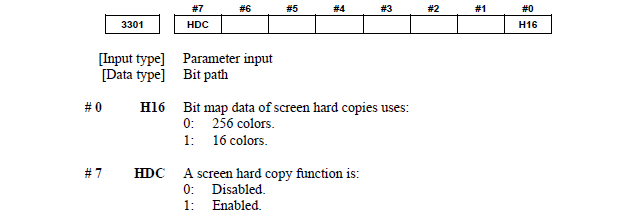
What Is Fanuc Parameter 14852 Bit 4?

Parameter 14852, Bit 4 controls the number of characters that can be displayed or entered in each fixed form field on supported Fanuc CNC controls.

When this bit is enabled, the control allows more characters per fixed form, effectively expanding the usable text length within those fields.

In practical terms, this means:

  • Longer text entries are possible
  • Descriptions and identifiers are less likely to be truncated
  • Fixed-form screens become more informative and easier to interpret

The exact behaviour can vary slightly depending on the Fanuc control series and software version, but the purpose of Bit 4 remains the same: increase character capacity per fixed form.


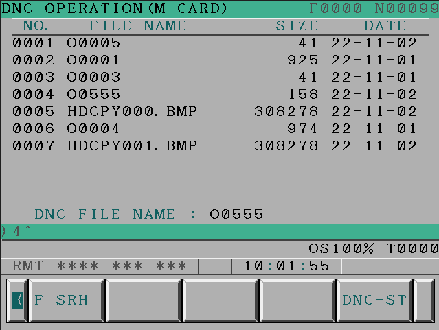
What Are Fixed Forms on a Fanuc Control?

Fixed forms are structured input screens used to quickly create program.

Typical forms:

  • Start of program
  • Call a tool
  • Call a cycle
  • End a program

I means the programmer does not need to memorise loads of G and M codes. The structures is created.

For more details on Fanuc macro variables and fixed forms, check our Fanuc Parameters that cover advanced control functions.


Why Increase the Number of Characters per Fixed Form?

Enabling Parameter 14852 Bit 4 can be particularly useful in the following situations:

1. Improved Program and Process Clarity

Longer character limits allow more information to be added in one keystroke.

2. Better Operator Understanding

Operators can see more meaningful descriptions without abbreviations, reducing the risk of misunderstandings on the shop floor.


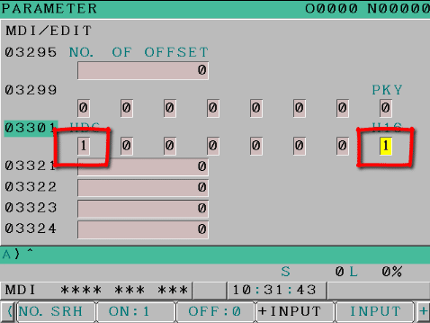
How to Set Fanuc Parameter 14852 Bit 4

⚠️ Important: Always back up parameters before making changes. Parameter behaviour can differ between control models.

To change parameters

You need to go to the setting screen in MDI. Now put a 1 in the parameter write box.

Fanuc CNC Parameter 14852 Bit 4

Put a 1 in here.

Compatibility and Control Versions

Parameter 14852 Bit 4 is commonly found on:

  • Fanuc 0i series
  • Fanuc 30i / 31i / 32i series

However:

  • Not all options are enabled on every machine
  • OEMs may lock or modify behaviour
  • Software revisions can affect results

Always consult:

  • The machine tool builder documentation
  • Fanuc parameter manuals for your exact control

Parameter, Risks and Considerations

While enabling this bit is generally safe, keep the following in mind:

  • Some custom screens may be designed around the original character limit
  • Consistency across multiple machines is important in production environments

Summary

Fanuc CNC Parameter 14852 Bit 4 is a small setting with a surprisingly positive impact. By increasing the number of characters allowed in each fixed form, it improves clarity, usability, and allows you to add more code with one quick insert.


Parameter 3109 Display W and G

People who know me know just how boring I am. Today I’m going to confirm this by getting very excited about this parameter.

Parameter 3109 bit 1 (#1) DWT will make the display of wear offsets loose that confusing W and G.

Stay here I’ll explain more.

CNC Training Call David: 07834 858 407


CNC Training Centre Reviews

30 five star ratings on Google (just saying)


Messing With Parameters Can Be Fatal!!!!!

Parameter 3109, to change this parameters first you need to go to the setting screen in MDI.

Put a 1 in the parameter write box.

Today we are going to change the parameter that stops the offset page displaying G and W.

Bit 1 (#1) DWT make this a 1 to stop this being displayed.

So when you change this parameter you won’t see a W beside the offset number in the wear screen. You also won’t see the G beside the tool number in the geometry screen.

I know for a fact when training people that this really confuses them. Especially the the G on the geometry screen.

This is it before with the W

Parameter 3109

This is it with the parameter change good old fashioned numbers.

Parameter 3109

As in the book

Parameter 3109

Bits n Bobs

When counting the bits in parameters you count from right to left so the first one on the right is bit 0 or sometimes known as #0

Other Parameters Of Interest


1300 Stops over travel alarm

1401 Cutting Feed-Rate 0% stops movement of machine

3101 Clear Screen

3102 Unlock Programs

3203 Clear MDI Screen

3204 Unlock Program 9000 to 9999 and 8000 to 8999 to Edit

3291 Wear Offset requires Key to Adjust

3401 Calculator Type Decimal Point or Integer

3402 G Codes that are Active When The machine is Turned On

5003 Retain Geometry when you Press Reset

6005 Allows the Use of Local Subroutines (Newer Control)

6050-6059  Allows you to Call a 9000 series Program with a G Code

6080-6089 Allows you to Call a 9000 series Program with An M Code

8134 3453 allows you to use ,R and ,C (Rads and Chamfers)

That’s it away you go.

Oh just one other thing before you go off and cripple your machine forever.

Do yourself a favour take a picture of the screen before you change a parameter. If you ain’t got a camera then you must have a piece of paper.

Even better back everything up.

Thanks

If you have been affected by any of the issues in this post or need CNC Counselling then contact me.

Or call us

If you want to learn to program CNC Milling Machines

Look no further Contact CNC Training Centre


Fanuc Parameter Write Switch

Call David: 07834 858 407

CNC Training Centre Reviews

30 five star ratings on Google (just saying)

Messing With Parameters Can Be Fatal!!!!!

To change parameters you need to go to the setting screen in MDI. Now put a 1 in the parameter write box.

Some more interesting parameters

3203 Clear MDI Screen

3401 Calculator Type Decimal Point or Integer

3402 G Codes that are Active When The machine is Turned On

6005 Allows the Use of Local Subroutines (Newer Control)

6050-6059  Allows you to Call a 9000 series Program with a G Code

6080-6089 Allows you to Call a 9000 series Program with An M Code

5003 Retain Geometry when you Press Reset


Oh just one other thing before you go off and cripple your machine forever.

Do yourself a favor take a picture of the screen before you change a parameter. If you aint got a camera then you must have a piece of paper.

Even better back everything up.

Thanks

If you have been affected by any of the issues in this post or need CNC Counselling then contact me.

If you want to learn to program CNC Milling Machines

Look no further Contact CNC Training Centre


Taking a Screen Shot Fanuc Control

CNC Training Call David: 07834 858 407


CNC Training Centre Reviews

30 five star ratings on Google (Just saying)

To take a Screen Shot Fanuc, you will need to have either a data card installed or a USB

Screen Shot Fanuc

MDI

In MDI I/O channel needs to be set (4) data card or (17) memory stick

Screen Shot Fanuc

Stick the Card in (or the stick)

Press and hold the shift key for about 10 seconds. You will see the clock stop. That’s how you know it worked. Time will stand still at this point and all the people around you will appear static.

Try not to panic, the world didn’t end. Your control just needs to ponder a while and think about what you just did.

Stop The Clock

Once it’s done your clock wil start again (phew).

Screen Shot Fanuc

Then press CARDScreen Shot Fanuc

Screen will show what is on the data card

Screen Shot Fanuc

The BMP files are your screen shots. You can then view them on your laptop or PC.

Now I know you are saying “what is the fuckin is the use of that”

Well It’s just so that I can show off my knowledge.

Parameter

If this does  not work then you may need to alter parameter 3301 bit zero and bit 7 need to be 1


Should look like this to make it work.

Screen Shot Fanuc

A good use is when you are changing parameters. There’s nothing worse than changing a parameter and trashing a £100,000 machine. Help is at hand, luckily you did a screen shot before you changed the parameter and you can view it and change it back.

With this parameter it wont work because you need to switch it on!!!

Good luck with the massive dent in the guarding and the bent tool. No screen shot will fix that.

Screen capture Fanuc, thanks for reading.


Overtravel Axis Fanuc Parameter 1300

Messing With Parameters Can Be Fatal!!!!!

Over-travel alarm, make this a thing of the past with this parameter

You first need to go to the setting screen in MDI.and put a 1 in the parameter write box.

Today we are going to change the parameter that stops the machine generating an alarm when it gets to the end of travel.

CNC Training Call David: 07834 858 407


CNC Training Centre Reviews

30 five star ratings on Google (just saying)

End Of Travel Alarm  Fanuc Parameter

Now I need to start by apologising to all the lovely people at Fanuc. All the years I have moaned and moaned about the fact that when you get to the end of the machine stroke on a Fanuc control you get a stupid alarm.

Actually I have been totally wrong and I offer my sincere apologies to all who have been hurt by my nasty comments about this.

If you set parameter 1300 BIT 1 (NAL) to a 1 then you do not get an alarm when you travel to the end of the machine stroke.

Fanuc Parameter 1300

This should make it work. If it doesn’t then maybe you should call the Samaritans.

Bits n Bobs

When counting the bits in parameters you count from right to left so the first one on the right is bit 0 or sometimes known as #0

Other Parameters You may Want to Change

3203 Clear MDI Screen

3202 Unlock Program 9000 to 9999 and 8000 to 8999 to Edit

3402 G Codes that are Active When The machine is Turned On

6005 Allows the Use of Local Subroutines (Newer Control)

6050-6059  Allows you to Call a 9000 series Program with a G Code

6080-6089 Allows you to Call a 9000 series Program with An M Code

5003 Retain Geometry when you Press Reset

3291 Wear Offset requires Key to Adjust

8134 3453 allows you to use ,R and ,C (Rads and Chamfers)

That’s it away you go.

This guy has more CNC Manuals than you can shake a stick at.

Oh just one other thing before you go off and cripple your machine forever.

Do yourself a favour take a picture of the screen before you change a parameter. If you aint got a camera then you must have a piece of paper.

Even better back everything up.

Or take a screen shot.

Thanks

If you have been affected by any of the issues in this post or need CNC Counselling then contact me.

If you want to learn to program CNC Milling Machines

Look no further Contact CNC Training Centre


Careers in CNC

View all current vacancies in CNC

Click here

Call David: 07834 858 407