Miyano CNC onsite training, is your production floor struggling to keep up with the demands of modern engineering?
Get your rapids to 100%
At CNC Training Centre, we specialise in bridging the skills gap with tailored Miyano CNC onsite training. By bringing our expertise directly to your facility, we ensure your team masters your specific Miyano machines in their own working environment.
Miyano lathes are world-renowned for their rigidity and accuracy, particularly in complex turning and milling operations. However, to truly unlock their potential, your operators and programmers need more than just basic knowledge. Our onsite training packages are designed to reduce setup times, eliminate programming errors, and significantly improve cycle times.
Why Choose Onsite Miyano Training?
Real-World Application: We train your staff on the exact Miyano models you own, using your tooling and your specific parts.
Zero Travel Costs: Minimise downtime and eliminate the expense of sending staff away for external courses.
Custom Curriculum: Whether you need to master Fanuc-based controls or complex twin-spindle, multi-turret synchronisation, we adapt the training to your skill level.
Immediate Return: Improved operator confidence leads to fewer scrapped parts and faster throughput from day one.
Old or young age is just a number.
From basic operation to advanced macro programming and live tooling integration, our 2026 training modules are updated to reflect the latest industry standards.
Miyano CNC onsite training
Don’t let high-end machinery sit underutilised. Invest in your workforce and see the direct impact on your bottom line.
Contact CNC Training Centre today to book your bespoke Miyano CNC onsite training session.
Heidenhain Q parameter programming is very similar to Macro CNC Programming for Haas and Fanuc.
Once you have grasped the concept of parametric programming you will find Heidenhain Q parameter programming easy to figure out.
Suitable for Fanuc, Mazak and Haas Macro Programming Lathe and machining centre
Haas, Fanuc or similar controls (ISO Mazak).
Make sure you have the Macro option on your control, it’s a real disappointment when you get all excited about this only to find you don’t have the option. Remember if you have a touch probe you will almost definitely have Macro installed on your machine.
Good news is you can buy the option, it don’t come cheap so sit the boss down and make him a cup of tea before you ask.
CNC Macro Programming Training Courses
What Use Will it Be?
This is where CNC Programming gets really exciting, welcome to the turbo charged world of Macro Programming for Haas and Fanuc type controls. There is so much exciting shit you can do with this I really don’t know where to start.
Write your own canned cycle
Yes you always dreamed of having your own personal G code, you can’t call it like Bill’s G code or something but you may have G271 or something which is personal to you.
Say you wanted a drilling cycle that changed speed half way down a hole or some daft thing well now you can do it.
Make A Set of Similar Parts
Imagine you had a bunch of parts that were similar, maybe the same holes but in different positions or a similar shape.
You could write a parametric (Macro) programme that would be completely adjustable and would make them all instead of having to keep writing similar programmes.
You can build these programmes and add to them as you get better and better and your ideas flood in.
I always say to students to start simple and build on your experience. Just using Macro in its simplest form will inspire you to go on to do greater things.
Interrogate Your CNC Machine
You can get almost any information you want from the machine.
Spindle Speed.
Position.
Datum.
Tool Length.
What tool is in the spindle.
Put the machine into an alarm state when things go wrong like wrong data is input.
And loads more.
You can even modify this information and send it back.
Do Calculations
Simple trigonometry.
Calculate feeds and speeds.
Simple maths.
Input formula and get answers.
I’m getting really excited just telling you this. It means you can add all sorts of functionality to your machine that you didn’t have before.
What Skills Will I Learn
Basic use of variables
Creating simple Macro programmes
How system variables work
How to write probing Macros
Creating your own G Codes
Create alarms to make sure your Macro users behave
We all know that programming can be complicated. So let me explain to you how it all works. This article explains the real meaning of Modal and non modal G codes.
Modal means that once a command is issued it stays in the control.
How Can you Actually Use This?
If you issue a G0 or G00 command the machine is in rapid and you do not need to re-state it.
Rapid means all motors are flat out, like a teenager in a Ferrari.
Every move from then on will be a rapid move unless you tell it otherwise. The G code that changes it must be in the same group. For example G0 G1 G2 and G3 are all in the same group a bit like The Beatles used to be.
The other day I was talking to a “young person” who hadn’t even heard of the Beatles. I mean fuckin hell, am I really really old or are they doomed to be forgotten?
Lots of software like Edgecam can perform full collision detection. You have a model of every tool and it’s holder. There is full model of the machine and all the work-holding.
Edgecam will even tell you if the flute length of the tool is too short!
Ok so that is all great so far but when we put this program in the machine to run there are three things the machine doesn’t know.
Can you guess what they are?
No it doesn’t know jackpot winning lottery numbers (that would be four things it didn’t know).
It doesn’t know where the part is in the machine coordinate system.
It doesn’t know how long the tools are (tool length offsets).
It doesn’t know the diameter of the tools.
Vital information wouldn’t you say?
So first of all we use the Work Offsets to tell the machine where the part is.
Please don’t worry if you don’t know how to do this after all this is beginners help with tool length offsets .
Your mates don’t know your reading it, you can tell them you already knew all this shit.
So in the picture above we would touch the spindle nose onto the Z datum of our work-piece. This would tell the machine where the part is in the Z axis.
This distance is input into our work offset table (in this case G54).
If we now program G0 G54 Z0 the spindle would rapid down to this position (G54 is where the values are stored).
We wouldn’t do this by the way cos the machine would crash.
Now The Tool Length
What we now need to do is take into account the length of the tool.
We would measure each tool length and store it in our tool length offsets file.
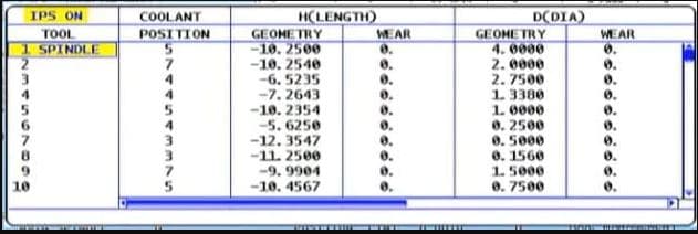
This is how they look on a Haas Machine
This tool length offsets file stays in the machine and is independent of your CNC Programs. So now any program can access this file.
So how does it do that?
It uses G43 and G43 says “ok get me a tool length offset”
G0 G43 Z3. H1
Which tool offset?? Well that’s the H number.
So the line above says to the machine rapid to Z3. Oh and by the way allow for the length of Tool 1 before you get there.
That’s the H1
So it gets the tool length from the tool length offsets file. It then does all the maths for you.
Actually it’s just a bit of simple arithmetic. Your (G54) work offset) minus your tool length.
Your tool will arrive 3mm above your component.
So whatever tool you called into the spindle with your M6 command you need to use the corresponding H number.
M6 T5 (Get tool 5 in the spindle) G90 G0 G54 X0 Y0 S1500 M3 (Rapid to X0 Y0 and start the spindle) G43 Z3. H5 (Rapid to Z3. but allow for the length of tool 5)
How do you measure the tools?
Well some people use a bit of paper!!!
And some buy one of these little babies.
“It’s just a light on a fuckin stick” I hear you say. But it’s so much more. I comes on at an exact distance above your part. And because it’s all spring loaded, if the tool carries on a bit it don’t bust anything.
Only cheap but do a great job.
And if your a very good boy you might get one of these for Christmas.
Auto tool measurement (yes it’s all done for you)
In the cases above we are storing the actual tool length in the offset file.
Now let’s take a look at that tool file again.
Some of my readers are very astute but before you start writing me an email or commenting on this article. “oh David it looks like you fucked up again”
I know……
Why are the tool lengths (Under Geometry) minus figures?
That’s because as always there are several ways to do this. What some people do (and I am not one of them) is……
They bring each tool down from zero return and touch on the part. This figure is then recorded in the tool length offsets file. And yes it’s a minus figure. Of course the G54 work offset would be zero in the case of Z.
Now I am not prepared to argue with you about this (your doctor told me not to). It’s just bad.
That figure has no relation to the actual tool length and you need to reset every tool for every Job!!
I’m saying no more I’ll just wait for the comments.
There is Only One Way
Actually there is something else to consider. (I know I
said I’m saying no more).
By setting your tool length the correct way (my way), the stored offset is the actual tool length and you can do a rough check with your steel ruler before proving your program.
Auto tool length measurement will always give actual tool length and so will a tool pre-setter. That means you can swap tools between machines.
Well it’s easy. Mazak machines have active offsets so the minute you do a tool change and get your tool in the spindle the tool lengths offsets are active. They also nearly always have an auto tool measurement system
.
Sorry if you are a Mazak user and you are thinking “this dozy bastard has made me read all this gratuitous shit for nothing”
Now’s the time to leave. Go on off you go.
Ok so what.
Mazaks also do this…….
When you write a G code type program for a Mazak you don’t need a G43 and you don’t need the H
M6 T5 (Get tool 5 in the spindle) G90 G0 G54 X0 Y0 S1500 M3 (Rapid to X0 Y0 and start the spindle) Z3. (Rapid to Z3. but allow for the length of tool 5)
Forget the G43 H5 shit…. soooo easy.
Those Mazak guys just don’t believe in stating the obvious and wasting your precious finger tips typing in a load of bollocks that the machine should know anyway.
Just remember you can change this by parameter if you want it to work the same way as your Fanuc or your Haas. Oh and you don’t care about increasing your carbon footprint with those extra finger presses.
That way you can put programs from your Fanuc into your Mazak and vice versa.
I noticed a common search in google is G80 G-code Fanuc.
CNC Machines use what we call canned cycles in a nutshell G80 cancels a canned cycle.
What is a canned Cycle?
To be honest I think it is a funny choice of words “Canned Cycle”.
My guess would be that all the information to drill a hole would be kept together in a “Tin Can” to use whenever you want.
I made this…….
First of all we program the cycle this is a G81:
G81 G98 Z-10. R1.5 F200. X55. Y55. F250.
The machine will move to the position X55. Y55. then it will rapid to 1.5mm above the part (this is the R1.5). It will then feed down to Z-10. at a feed-rate of 250 mm per minute F250.
Finally it will use rapid to come out of the hole.