Category Archives: News

How to Use FANUC Manual Guide i engraving Doosan Lynx

FANUC Manual Guide i Engraving on a Doosan Lynx 300M

FANUC Manual Guide i engraving is one of those things that often looks more complicated than it really is.

Now I admit to having a few “issues” with Manual Guide i  but when it comes to engraving I have to admit it’s quire simple.

Not well explained, sorry I’m doing it again. Anyway once you get how it works and what it wants to know it’s easy

If you have a CNC lathe with a C axis and driven tooling, you can do much more than turn diameters and face components. You can mill flats, drill cross holes and engrave text directly onto the component.

Loads and loads of shit. So much fun without taking down your pants.

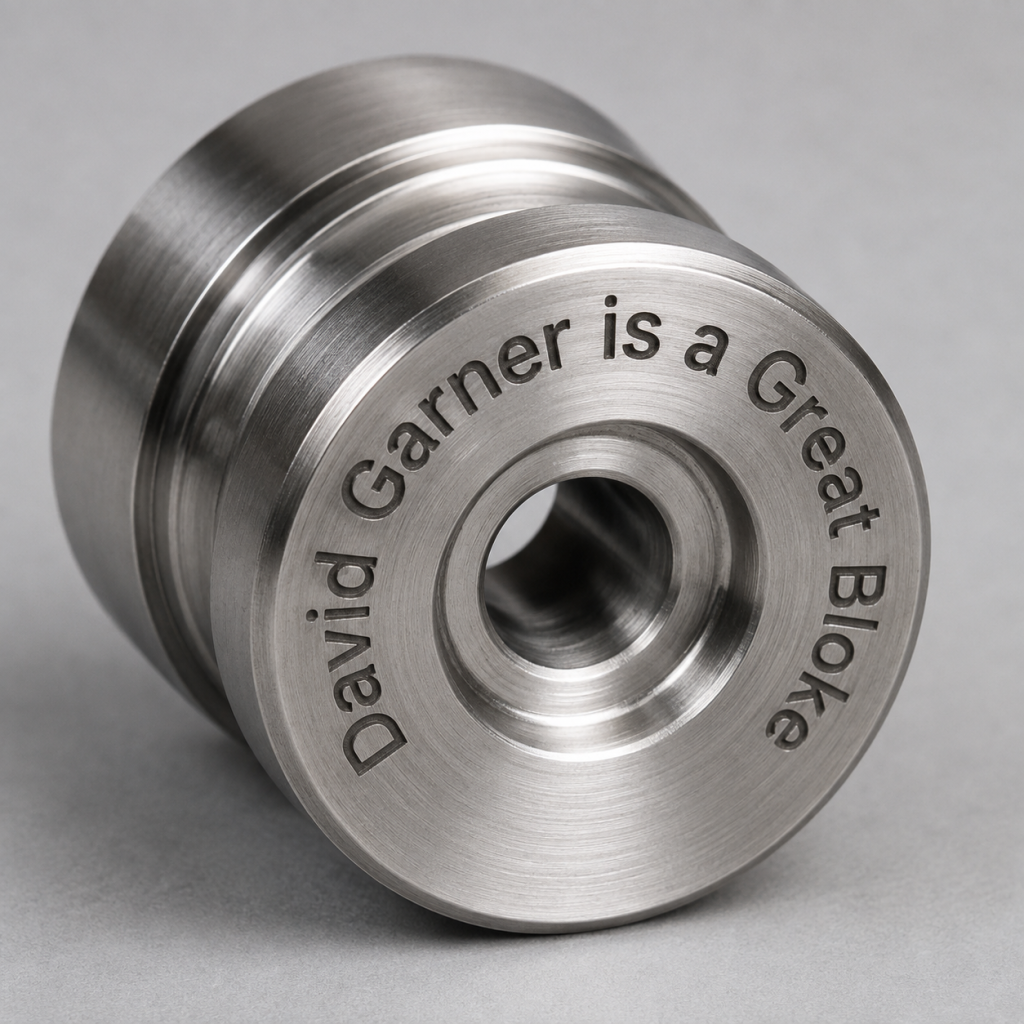
On the Doosan Lynx 300M, you can engrave on the front face of a component or wrap the engraving around its outside diameter. It can be straight across the front face or rotated around it.

FANUC Manual Guide i engraving

This type of C-axis engraving is ideal for adding:

  • Part numbers
  • Batch numbers
  • Serial numbers
  • Company names
  • Material specifications
  • Inspection references
  • Simple identification marks
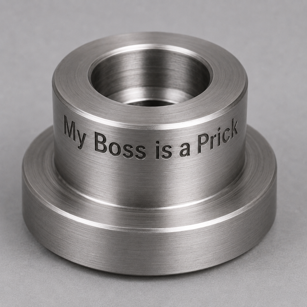
  • And the most common which is rude comments to make your mates laugh

Manual Guide i makes the process quite straightforward. You can create the engraving conversationally rather than calculating and programming every individual movement yourself.

FANUC describes Manual Guide i as a conversational programming system for turning, milling and combined machining applications. You can read more about its capabilities on the official FANUC Manual Guide i website.

What Does the Machine Need?

Before you attempt any CNC lathe engraving, the machine must have the correct tooling.

I’m working on a Doosan Lynx 300M today children and it’s a lovely machine.

Your Machine Must Have

A programmable C axis

Driven or live tooling

Axial driven-tool holders for front-face work

Radial driven-tool holders for work around the diameter

FANUC Manual Guide i

It’s All About the C Axis

The C axis allows the main spindle to be positioned and controlled like a rotary axis.

Instead of simply rotating continuously as it would during a turning operation, the spindle can move to an exact angular position. It can then coordinate that movement with the machine’s other axes.

The driven tool provides the cutting of the letters.

Put those two things together and the lathe begins to behave like a milling machine.

The most confusing thing with engraving is the positioning but once you get this it’s easy.

Fortunately you get to test all this in the graphics. Anyway you might get some weird shit but at least it’s only fresh air.

Engraving on the Front Face

Face engraving on a CNC lathe is normally completed with an axial driven tool.

How an Axial tool looks

The tool points towards the front face of the component, parallel to the machine’s Z axis.

The engraving movement is produced by coordinating the machines X axes with the C axis.

Exactly how the operation is displayed will depend on the version of Manual Guide i and how the machine-tool builder has configured the control.

Begin by selecting the appropriate FANUC engraving cycle in Manual Guide i and choosing the front face as the machining surface.

You will then enter the information required by the cycle.

This will normally include:

  • The text to be engraved
  • Character height
  • Engraving depth
  • Starting position
  • Text direction
  • Cutting feed rate

Manual Guide i then creates the necessary tool path.

One important consideration is the amount of room available.

The further the text is positioned from the centre of the component, the more space there is around that radius. Text positioned very close to the centre can become cramped because the available distance reduces rapidly.

Always use the Manual Guide i graphics screen to check the result before running the program.

That little graphics button can save a lot of frustration.

Engraving Around a Diameter

Engraving around a diameter is where having a C axis becomes particularly useful.

For this operation, we normally use a radial driven-tool holder. The engraving cutter points towards the centreline of the component and cuts into its outside diameter.

FANUC Manual Guide i engraving

The Z axis controls the position along the length of the component while the C axis rotates the component.

This allows the text to wrap around the diameter.

You could engrave a part number around a collar, add a company name to a component or mark a round part without removing it from the machine.

The control must convert the linear length of the text into rotary C-axis movement.

The component diameter is important an error in the diameter entered can alter the size and spacing of the completed text.

Choosing an Engraving Tool

For most driven-tool engraving, a small carbide engraving cutter works well.

These are often pointed cutters with an included angle such as:

  • 30 degrees
  • 60 degrees
  • 90 degrees

A cutter with a smaller included angle produces a finer line, but it may also have a more fragile tip.

A 90-degree engraving tool is strong and readily available. However, its cutting width increases quickly as the engraving depth increases.

This is why engraving depth is important. You can even use a spot drill.

You generally do not need to go very deep.

For basic identification work, an engraving depth of approximately 0.05 to 0.15 mm will be sufficient. The correct depth will depend on the material, cutter angle, surface condition and required line width.

Engraving cutters have very small tips and do not enjoy being treated like roughing tools.

Setting the Engraving Tool

The tool must be set accurately but it is no different to any other radial tool so set it in the same way.

For front-face engraving, the tool’s Z length and X position are set.

For engraving around the outside diameter, the radial tool position is particularly important because it controls the actual engraving depth.

A small setting error can make the engraving:

  • Too shallow
  • Too wide
  • Uneven
  • Completely invisible
  • Much deeper than intended

It is a good idea to prove the Manual Guide i engraving operation on a test component or a scrap piece of material.

Add some to the offset to begin with the tool slightly clear and adjust the offset gradually until the engraving looks correct.

Speeds and Feeds for CNC Lathe Engraving

Engraving speeds and feeds depend on the material and the cutter being used.

A small carbide cutter will often use a relatively high rotational speed. However, remember that the driven-tool spindle on a CNC lathe may not have the same speed range as the spindle on a machining centre. It will probably end up being flat out.

Start conservatively and follow the cutter manufacturer’s recommendations where they are available.

Sometimes the bearings are not too good in driven tools especially when they get older. Might be worth warming it up at around 1000 rpm for a while before taking the speed too high.

These tools should be serviced but no one can ever be arsed to do it. Maybe you will but it’s well worth it.

The cut is normally very light, so the biggest risks are not spindle load or horsepower.

The biggest Risks

  • Breaking the cutter tip
  • Running the driven tool in the wrong direction, try starting it at slow rpm then take it up, that way you can see it.
  • Using the wrong engraving depth
  • Selecting the wrong machining surface
  • Entering the wrong component diameter
  • Starting at the wrong angular position
  • Running too close to the chuck, you probably won’t spot this in the graphics.

Check the driven-tool direction before bringing the cutter into contact with the component.

Proving the FANUC Engraving Cycle

Before running the engraving cycle, use the Manual Guide i simulation or graphics display.

Check that:

  • The text is spelt correctly
  • The text faces the correct direction
  • The starting point is correct
  • The characters are not mirrored
  • The correct machining surface has been selected
  • The tool is on the correct side of the component
  • The engraving fits inside the available area
  • The approach and retract movements are safe
  • The tool holder has sufficient clearance, again you won’t spot this in graphics.

Prove the Operation on the Machine:

  • Single Block
  • Lowest rapid override
  • Start with low feed override
  • A safe starting position
  • You can move datum and machine in fresh air to test.
  • Be particularly careful when using a radial driven tool close to the chuck.
  • The cutting tool may have plenty of clearance, but the body of the driven-tool holder or turret may not.
  • The chuck is unlikely to move out of the way simply because you have made a mistake.
  • You may need to reset the C Axis datum so that you miss the jaws of the chuck.

    FANUC Manual Guide i

    The main advantage of the engraving feature is that you do not have to calculate and program every letter manually.

    You tell Manual Guide i what you want to engrave, where you want it positioned and how large it should be.

    The control then generates the machining data and allows you to inspect the toolpath.

    That does not remove the need to understand what the machine is doing.

    Conversational programming is there to help the programmer. It is not there to replace checking.

  • Graphic can give you a false sense of security. Don’t forget that the grapics does not allow for your tool length. I also knows nothing about the work offset.For more articles about conversational programming, program conversion and using the control, visit the Manual Guide section of the CNC Training Centre website.

    All Shapes and Sizes

    First of all on your cutting conditions tab give clearance above your part (C)

    FANUC Manual Guide i engraving

    Give it your feed rates and then the PLANE SELECTION.

    This will give you two choices. It might be helpful to think of C as your Y axis.

    This would be the front face (XC)

    This would be wrapped around the diameter of your part.

    ZC Result

    This is what ZC would give u

    s

    Position Tab

    Hit the POSITION tab

    FANUC Manual Guide i engraving

    H-10. means I am 10mm away from the front face of the part.

    V20. is the angle, normally this can be zero but it is where the text is placed around the diameter.

    The base position would be the radius that I am placing the text on. B72.5 would mean I am on a 145mm diameter. Were you to place text on the front face then you would chose XC and this B figure would be zero

    You have a choice of full or half size characters.

    The CHAR SIZE id the height of your lettering

    ANGLE is the angle that the test is at chose the icon

    Click the STRING tab and type in exactly what you want to say

    FANUC Manual Guide i engraving
    The Actual Text

    Final Thoughts on FANUC Manual Guide i Engraving

    The FANUC Manual Guide i engraving feature is very useful on the Doosan Lynx 300M.

    Because the machine has a C axis and driven tools, it can engrave both:

    • Across the front face of a component
    • Around the outside diameter of a component

    Once the tool has been set correctly and the cycle information entered, Manual Guide i completes most of the difficult programming work.

    The important points are to select the correct machining surface, enter the correct component diameter, keep the engraving depth sensible and check the graphics before pressing Cycle Start.

    As always, prove the program carefully.

    The machine will engrave exactly what you tell it to engrave.

    Unfortunately, this includes spelling mistakes.


I Love Guide i

Category : New Stuff News

Now I know in the past I have been inclined to say some pretty rude things about Fanuc Manual guide.

Well today I’m here to make amends please Mr Fanuke, as the Americans call him, forgive me it was pure ignorance.

Right now that’s out the way. I could write a massive blog about all the shit things but no there are some great things.

I think the more you learn about something the more you seem to like it. Like all these people who slag off electric cars, funny how they have never actually bought one. I have one and I love it.

Let me make a amends today so it;s official “I Love Guide i”

Manual Guide i is great for editing, fixed forms are awesome and graphics are less crap than all the others.

I Love Guide i, Some things you might not know

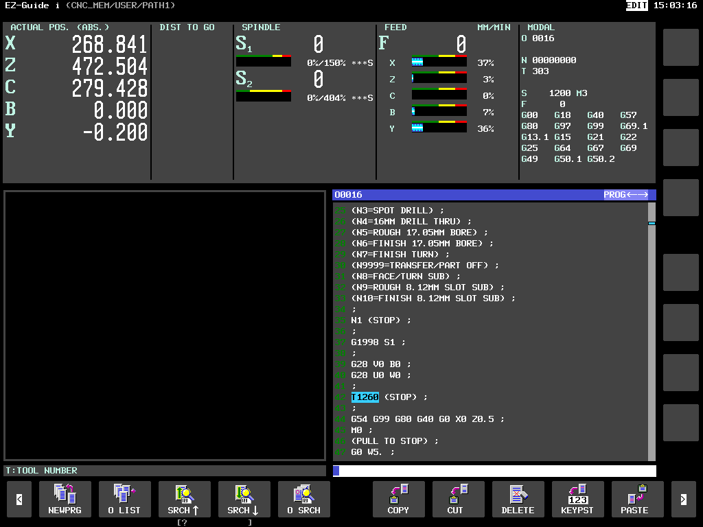
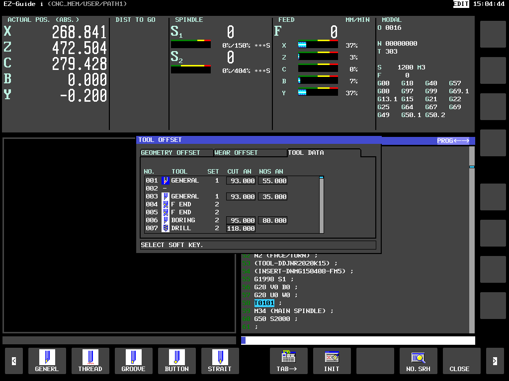
You can click on a tool like in this picture T0101 then press INPUT

I Love Guide i

And it will jump to the tool file.

I Love Guide i

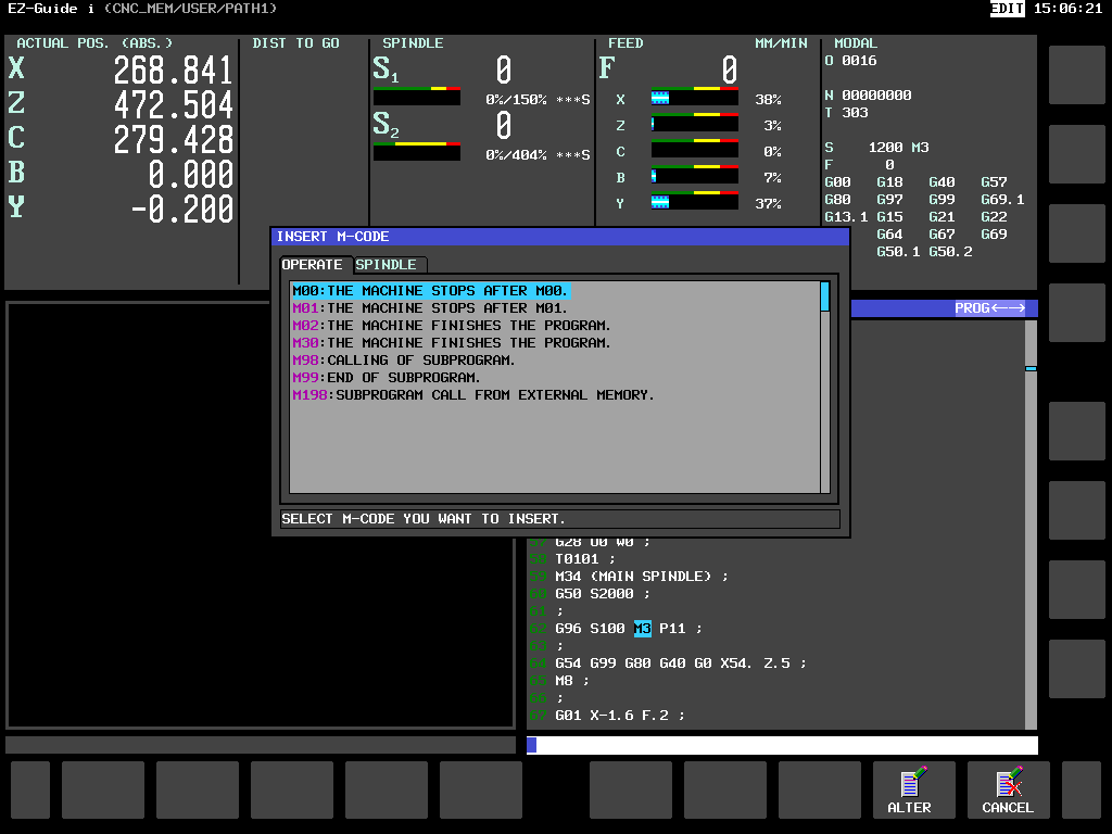
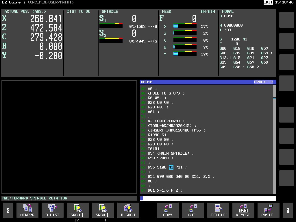
Now try clicking on an M code and press INPUT.
I Love Guide i

Wow an M code list comes up. I recon that’s impressive and very useful taboot.

I Love Guide i

I you have it and you don’t use it then you bloody well should. another reason is that when you click on a G code or M code down the bottom left it tell you what it is. Don’t you just love it. Oh and one more thing if you can be arsed to put all your tool descriptions in it will tell you what they are too.I Love Guide i
Stick around to learn more


Loading Tools on a Doosan DNM


CNC Training Centre Reviews

30 five star ratings on Google (just saying)

There are several ways of Loading Tools on a Doosan DNM. The first is the most simple. Don’t forget this is random tool changer so it’s no good looking in the tool drum. Read this article first if you don’t understand how a random tool changer works.

Just call out the tool you want for example T6 M6 and then load your tool. Your tool has now become T6.

M45 To The Rescue

The other way of Loading Tools on a Doosan DNM is to use M45

Loading Tools on a Doosan DNM Access Tool Table

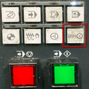
So to acces the tool table on a Doosan DNM press this button.

Doosan Tool Drum

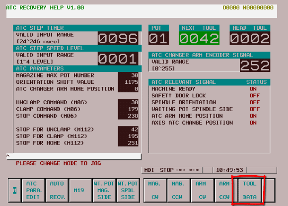
This screen is displayed.

Loading Tools on a Doosan DNM

Press TOOL DATA button

Loading Tools on a Doosan DNM

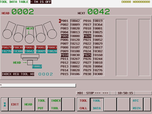
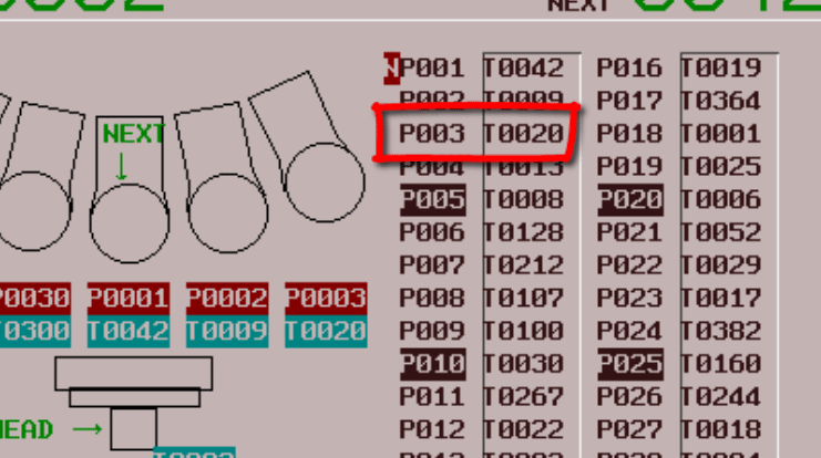
This is your tool table that tells you where everything is in the Doosan Tool Drum.

This tells me that T20 (Too20) is in pocket 3 (P003).

Loading Tools on a Doosan DNM

Love It Or Leave It

From this screen you can decide what tools you want to keep and what tools you want to replace.

It’s a good idea to keep an actual list of what tools are in your machine.

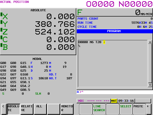
If I wanted to use pocket three then call it in MDI tool 20 (M6 T20).

Doosan Tool Drum

Now you can load your tool, if the pocket is empty, or exchange it with this tool.

Loading Tools on a Doosan DNM

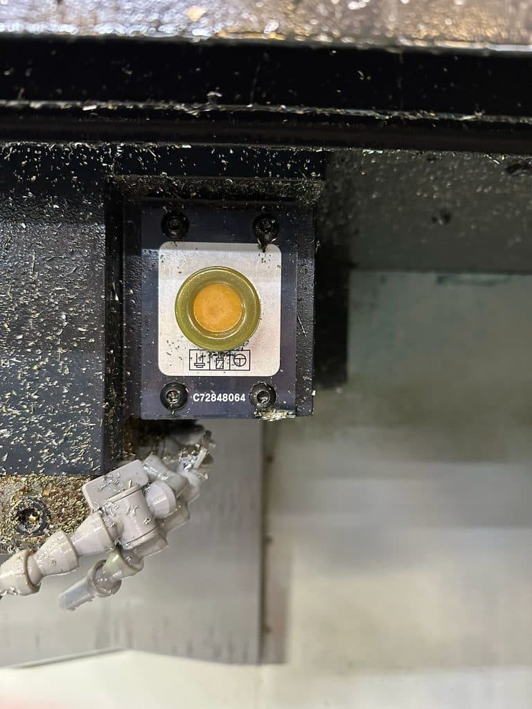
This button will release the tool if you are in a manual mode.

The tool can be heavy or stick in the spindle so be prepared for it to drop. It may be heavy so you could put a piece of wood under it to support i

From now on your tool will be tool 20 (T20).

Please don’t call it anything else because it will just ignore you.

“Read More”

CNC Course

Category : New Stuff News

CNC Course

Precision Machining with Expert Training

If you’re looking to enhance your CNC machining skills or start a career in precision engineering, these CNC courses are the perfect opportunity.

CNC Course

Based in Barwell, Leicestershire, THE CNC Training Centre offers hands-on learning with real CNC machines and simulators, ensuring you gain practical experience in CNC milling, turning, and advanced mill-turn operations.

Why Take a CNC Course?

CNC (Computer Numerical Control) machines are essential in modern manufacturing, used in industries such as aerospace, automotive, and medical engineering.

Learning how to program and operate CNC machines can open up excellent career opportunities and improve efficiency for businesses.

The CNC courses cater to:

•Beginners looking to enter the industry

•Experienced machinists wanting to upgrade their skills

•Companies seeking to train their staff in the latest CNC programming techniques

What The CNC Courses Cover

We provide two-day intensive training courses, offering a structured learning approach to CNC programming and operation. Our 2026 courses include:

•Introduction to CNC Programming – Learn the basics of G-code, tool paths, and setting up CNC machines.

•Advanced CNC Milling and Turning – Focus on complex multi-axis machining, tool compensation, and cycle optimisation.

•Mill-Turn Programming – Master advanced mill-turn techniques on real machines.

Why Choose Our CNC Training?

•Expert Instructor – Experienced CNC machinist who offer industry-relevant insights.

•Small Class Sizes – We ensure personalised instruction to maximise learning.

•CNC Training Centre is equipped with the latest CNC Simulators.

CNC Course

Enrol in a CNC Course Today

Whether you’re a beginner or an experienced machinist, these CNC courses will help you improve your skills and stay competitive in the industry.

Contact us today to book your place on our next CNC course and take the next step in your machining career.

Get in Touch

Contact CNC Training Centre


Start your journey in precision machining today with our expert-led CNC training!


CNC Programming Using CAD/CAM

CNC Programming, When will it not be needed?

CNC Programming Services Call David: 07834 858 407


CNC Training Centre Reviews

30 five star ratings on Google (just saying)

858 407

Are we fast approaching the day when we don’t need to know anything about programming in terms of G code etc.

CNC Programming
Tool Holder (Patent Pending)

Short answer is yes.

I was watching an interesting video on youtube the other day. This guy (seemed like a very clever guy) had bought an old CNC Lathe, a Mori Seiki.

I don’t think he had ever done any machining or general metal work type stuff.

His approach was untainted shall we say. He’d certainly never done any G code type CNC Programming.

CNC Programming

He immediately looked for software which would program this machine and said how in the past it would have been programmed with G code by hand.

Anyway he got something like One CNC or Fusion 360 and created a program. He went on to produce quite a few parts.

Really this proves that you don’t need to know G Code programming, or does it?

Because I am an old dinosaur and I make a living partly from teaching people G code type CNC Programming, I wonder if people like me are clinging on to these old skills and not moving forward.

It reminds of the times when CNC’s were first introduced all the old guys used to say they would never replace the capstans and autos. I remember my dad beating my first chess computer and saying it was just a gimmick.

CNC Programming

So what problems do you get when programming straight from software. Actually if you know what you are doing the answer is none. But do you know what you are doing?

The danger is when the person using the CAM system doesn’t really understand about work-holding and tooling.

I bet the aforementioned guy had some serious problems with his selection of cutting tools.

“Read More”

Careers in CNC

View all current vacancies in CNC

Click here

Call David: 07834 858 407