That’s when I sorted out the number of passes thing. If you don’t know how to calculate the number of passes in a threading cycle then you should read the article above.
I am always amazed that so many companies still don’t use G10 in their CNC programs. If you know you know.
I must admit I fuckin hate a lot of the things that young people say like “can I get a Latte”. (Get behind this fuckin counter and make it yoursef if you want to “get it”).
Anyway I kind of like “If you know you know”
No G10… Is this you?
I am sure you have your reasons which I will accept. But if your reason is that you don’t understand it then that’s just not good enough.
So you make a part, it’s all setup and you need to break it down.
If you can fix the work holding in such a way that you can reload it in exactly the same place then you need G10.
Let me explain, watch this video to see how single point location works.
G10 No need to spend loads of money.
You could just bolt a sub plate to your machine table so that vices and chucks etc can have dowels to locate them.
But the main idea is that you can relocate your work holding in exactly the same place every time.
Using G10 on a Fanuc Type Control
This is your work offset page on a Fanuc control.
These figures are written in by hand or by automatic setting.
If you had written this line in your program.
G90 G10 L2 P1 X-440.500 Y-265.200 Z-443.00
They would have been written in automatically when you ran the program.
So the work offset page could have any values in G54 but as soon as you run your program this G10 command will replace them with its preset values.
Make Sure Your in Absolute
Try not to forget the G90 (Absolute) because you may accidentally be in G91 (Incremental). What would then happen is it would add these numbers to what is already in the work offset. Oh dear me.
In G90 it will always replace them.
You can write to G54 G55 G56 G57 G58 or G59 just by changing the P number.
The letter O is only used for a programme number and a GOTO statement on a Fanuc Control. It’s important not to get it mixed up with the number Zero. So we should really say G zero one ( G01 not GO1 ).
So remember it’s G01 not GO1 (Zero not letter O)
A good solution is to miss it out where possible G1 not G01 etc.
This is part of a series of articles designed to cover basic CNC Programming.
When I first learnt to programme, before the First World War, I still remember how daunting the thick yellow Fanuc Manuals were. The Japanese were learning to speak English and we were learning to speak G Code.
Fanuc Manuals
Fanuc manuals are just like the yellow pages. A note here for you young people who might not know what yellow pages are (no it’s not like someone pissed on the photocopier)
Long before Google we had these thick yellow books and we used them to find stuff like if your mam needed to get the outside toilet unblocked or something.
None of this stuff was in the Fanuc manuals but you could easily get them mixed up cos they looked very similar.
I can honestly say when I was learning Basic CNC Programming I read the old 6M Fanuc manual from cover to cover. The Macro bit was just like another planet to me. Some things I had to read over and over again to understand.
Some of it was so badly written you kind of had to guess what they meant.
In the Beginning
Every now and then I used to go right back to the beginning and read the basic stuff again. Believe me, every time I would find something I didn’t know, mind you I didn’t know much then anyway.
Try it later and if it doesn’t work I’ll give you your money back.
Okay enough of this bullshit and verbiage let’s talk about G codes.
Useless information but anyway, now I’ve said it. Don’t tell your mates down the pub because you will probably bore them shitless.
I often begin my training courses by saying “you only need to know four G codes to programme a CNC, it really is that easy”
G0 G1 G2 G3
(Please smart arses don’t contact me.)
What that means is that you can get round any shape with straight lines G1 and circles G2 and G3. Oh and you need to quickly get to the part so use G0 rapid.
G00 can be G0 (Never GO as in letter O) G01 can be G1 (Never GO1 as in letter O) G02 can be G2 (Never GO1 as in Letter O) G03 can be G3 (Never GO1 as in letter O)
G00 or G0 commands a rapid move. That means the axis will be flat out. Maximum foot to the floor, shit off a stick as we say in the Midlands.
A common mistake with rapid moves is to assume that the axis will all move in a straight line like a bullet from a gun.
Not true. Because each axis is flat out one axis may arrive before the other. The rapid on your X axis could be slower than your Z. Anyway you get what I mean.
Why do I need to know this?
Easy because if something is in the way then you might hit it. That is if you assume the movement is a straight line.
Now lets see.
Move down in Z
G0 Z5.
Then a nice straight line G0 X130. Z-30.
But meanwhile in the real world
It’s obvious really.
Just think for a moment:
If both X and Z rapid motors ran at the same speed. Then each axis will move the same amount until one reaches its destination.
Looks like this.
Z has 30mm to move in total so they will both move 30mm. This will make a 45 degree line.
Ah but X is not finished yet. X will carry on and finish its move in a straight line.
If something is in the path of your rapid move you may need to programme your axis separately to be sure not to hit anything.
G00 X130. Z-30.
Could be:
G00 X130. ; Z-30.;
Please don’t repeat the G00 (you know it will piss me off).
Now G01 ( G01 not GO1 )
G01 is a linear feed. It means feed in a straight line. Just like stretching a piece of string between two points. It can be just one axis or two simultaneous axis. You can even programme X Y and Z all in one line of code.
So this is what really separates a CNC from a manual machine. Remember how hard it was to machine an angle on a manual milling machine? Or a taper on a lathe.
You do?
Well on a CNC Machine we just programme the end point. It will then machine a straight line from it’s current position to the programmed point
If your machine was at X50. Y0 and you programmed a line
G01 X55. Y-200. ;
You would get an angle.
Ok what’s wrong in this picture?
Just to see if you are not a robot?
Yes congratulations but what is wrong with the line.
G01 X55. Y-200. ;
The Feed-rate
Yes with G01 you need a feed-rate. Don’t repeat the feed-rate, you only need another feed-rate when you want to change it.
G01 X55. Y-200. F100. ;
Don’t forget you can programme X Y and Z together and it will still be a straight line just like you tied a piece of string between the start and end point.
F100. means feed at 100mmper minute.
CNC Turning
On a manual lathe you would have to set up a compound slide to just machine an angle.
Mmm very skillful and I’m sure it’s loads of fun.
On a CNC Lathe this is just one line of code and some Basic CNC Programming!!
What About 3 Axis Rapid?
Yes you can programme 3 axis together in rapid move. It’s definitely the quickest way to get to the part.
G0 X50. Y20. Z3.
I would definitely advise using it but, and there always is one, just be real careful nothing is in the way. Don’t blame me I’ll just say I never met you.
Oh just one more thing as Columbo would say.
You could use a very high feed instead of a rapid move. That way you really would guarantee a straight line. I’ve never done this but it just came to me in a flash.
So there you have it G0 is rapid ( never GO letter O).
G1 is linear feed, remember G01 not GO1 (Not letter O)
Thank you for reading my article ( Basic CNC Programming G01 not GO1 )
A Femco, yes they let me out again, tagged but free to train my victims.
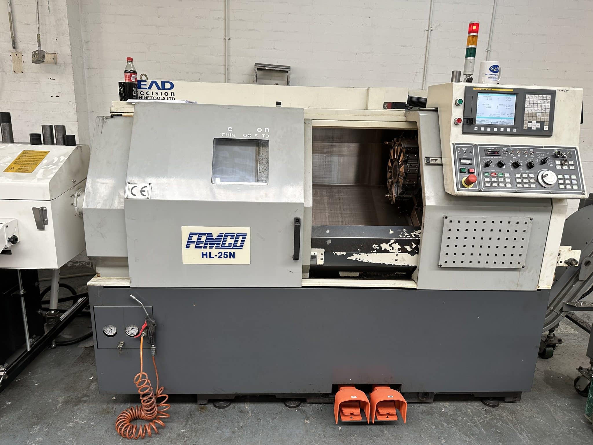
Sooo, today I got to work on a Femco not to be confused with products designed to keep your private parts smelling nice n fresh
As is often the case there were no machine manuals. This is not like pissing into the wind no no this is pissing into a fuckin sunami with a water infection (tsunami so that’s how you spell it).
This one is the Femco HL 25N, Fanuc Oi TD control with macro, whoopee.
Nice simple two axis lathe, absolute doddle.
No Manuals, No Doddle
Anyway I couldn’t get it to bloody budge. It was like trying to get a teenager out of bed at 6am in the morning (fuck you).
It does everything except for Zero return, Jog and Rapid mm mmm. Apart from that it was great.
Definitely won’t be able to bull-shit my way out of this one.
Hand-wheel, check.
Spindle on off, check.
Index turret, check.
Coolant on, check.
Light on, check.
I suppose I could tell the customer that it was a demo machine and never designed to actually move around. Only thing is they want to make stuff on it so that idea wouldn’t work.
Anyway there was only one way to do this, we decided to take a very logical precise and scientific way to solve this problem of the lazy turret.
Yes you guessed it, we just keep pressing buttons until something happened. Pushing buttons on the fly as it were.
Low and behold it worked.
Is it me or is it outright blindingly shit-faced obvious????
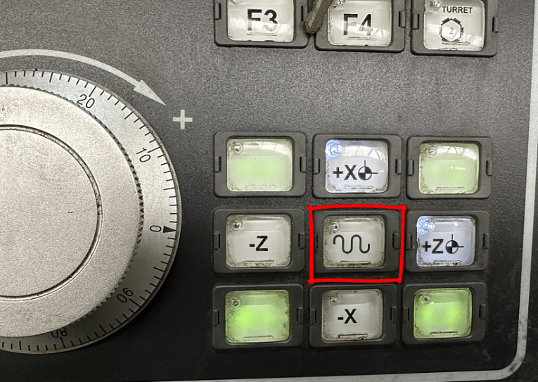
Please tell me no. You hold the button in the middle as you press the outside buttons. Works for RAPID, JOG and ZERO RETURN
Normally that button is to change the moves to rapid. Not here, this machine has a rapid mode.
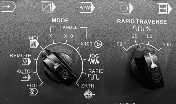
In fact everything on this dial except for the first four selections.
Sooo. That meant we could zero return the machine, phew.
Only an hour into the training and we’re just moving the machine around. But honestly how would I fuckin know. I mean without a manual and unless you worked one of these beasts before you couldn’t know.
Talking of bull-shit it’s something I never do, I mean yes I do bull-shit everybody does especially after 14 pints of lager.
No I mean when I’m training people. I’ve learnt it’s best to say sorry I don’t know. Then afterwards I will spend hours making sure I do know.
Some trainers, and you know who you are, will gloss over shit that they don’t know and it’s easy to do but in the long run it’s not good for anyone.
Anyway It’s Not Over Yet.
Next challenge. Tool arm, all I want to do is get it to rear it’s ugly head. It wont come out.
Tool Measurement arm please reveal yourself. Honestly this one is bonkers.
Have you guessed it yet?
You hold down the ready button (that’s the one that switches the machine on) and simultaneously press P SET and voila. It appears.
You just can’t know this stuff without a manual. Can’t blame the customer as he bought this machine at auction so it’s always a bit of a lottery.
Anyway once all the, shall we say “teething problems”, are out the way it’s time to have some fun.
Femco Let the Madness Begin
Measuring Tools
With the measuring arm down you can do what you want. So if you wanna smash or just bend this thing it’s dead easy.
Rapid Full Wack TICK
High Feed TICK
Index Turret TICK
Index Turret Whilst Checking a Tool TICK (I love this one)
Feed as fast as you want whilst checking tools TICK
Anyway that to one side at least it clears the the wear offset each time you check the tool. Which in my experience does not happen on all machines so beware.
It also jumps to the correct offset and displays the offset table. Some machines don’t even do this. Means you can measure the wrong tool mmm.
The tools on this turret are very close together. I mean it’s got 12 tools and they are crammed in. It’s like trying to breakdance in a Mumbai shopping centre on Black Friday. So extra care is needed.
Watch Out For
Tools hitting the chuck when proving out. Don’t forget that the tool you are watching has one sat right underneath it just waiting to kick you square on in the knackers when it clobbers the chuck.
Also when using tool measurement arm you can hit it underneath with the tool below. Now this shouldn’t happen but if you have some unusual weird tool that sticks out too far, it can hit.
When Measuring Tools Do This
Drive the tool in the opposite direction first. That way if you are in Rapid mode by mistake you will spot it.
It is also important to measure the tools at the same feed-rate. This ensures constant measurement and consistent figures.
Mazaks and the like just fix the feedrate when the arm is down so you automatically get the same feedrate regardless of dial position.
When I grow up (which people say I never will) I’m going to make a tool measurement arm that does all these things so you can’t trash it.
Always keep the rapid down real low when setting up a CNC machine.
No more than this.
Femco, It’s A Cool Dude
There is a massive difference between machines with regards to what they allow when using a measurement arm.
Like parents some let the kids do what the fuck they want and when they visit you your house gets trashed and you have to pretend it’s all ok (bastards).
This Femco HL 25N CNC Lathe is the “Hippy” of machine tools. It’s the laissez-faire, the “don’t give a flying fuck”, the “stay on ice man” machine tool. Anyway you get it.
It doesn’t have any respect for your welfare or your wallet. You wanna break this thing go ahead and do it, it’s cool with that.
Joking Aside
This Femco is a second hand machine bought at auction and I recon it’s half decent. The previous owner obviously looked after it. No battle scars, no dents in guards or cracked windscreens. Sounds lovely too, spindle nice n quiet and no axis noises.
Once you get your head around the weird protocol shit it’s easy. Just remember to press the buttons in the right order.
Setting the work offset is easy too. Call out the tool MDI (lay off the reset button) then press this
The work-shift screen will manifest.
Then press this.
You will see the work-shift figure update.
Job done just don’t press reset otherwise tool offset may be dumped and everything goes tits-up.
This Femco has Fanuc Oi TD
It has Macro which is great, oh and somebody changed the brackets around. Just give me a minute I’ll explain.
On a Fanuc control like this it’s a pain the the arse to put comments into your programs. That’s because you have to press a million combinations of buttons to get to the curved brackets.
Anyway by changing a parameter you can make the square brackets into curved brackets making it all much easier.
Fanuc buried access to these extra buttons for brackets and commas and stuff like that deep in the bowels of the control. Without a metal detector and a private investigator they remain the fourth secret of Fatima. For my thick readers this link will save you googling this.
Graphics
Well what can I say. If this was 1980 I’d be saying these graphics are cool. Unfortunately they are in a time lock a nice way of saying crap.
Anyway I’ve done this rant a million times so I’m not repeating it as much as I know you want me to.
If you have graphics then I will always recommend their use.
If you make a daft typo type error or like me you forget that in G74 the Q value can’t have a decimal point. Then the graphics will show an alarm.
Before
G74 Z-25. Q5. F.2:
After
G74 Z-25. Q5000 F.2:
This is way better than finding it at the prove-out stage.
You have to use machine lock and just run the program in memory as normal. Machine lock switch has to be pulled out to work (to stop you accidentally turning it on)
Use the feed potentiometer to speed up and slow down the graphics.
Be careful using graphics with machine lock. Zero return the machine BEFORE and AFTER use of machine lock.
Setting Speed In Manual on Femco
No need to program in MDI all you need is this.
Just be careful to leave it turned down or you may get a nasty shock when you start the spindle.
Turret
The turret is absolute “dog shit off a stick fast” so be careful. You can’t select individual tools so it’s a bit like playing roulette trying to get the tool you want. But at least it’s bloody quick. Shame there is no cuddly toy prize when you select the right tool with your first press of the button.
Inches “Oh my God”
For you Americans just say millimetres “holy goddam shit”.
The previous owner had this machine in inches. Now you can’t just program G21 it’s a common misconception. The G20 or G21 are just a check. It will just alarm out if you are in inches and you program G21 to mm. It’s like a shot across the bows, a warning.
Sorry suckers it’s a setting. Oh and to completely fuck you over it does not convert the program. It merely changes the decimal place. Useless. Other controls are available that convert. Never mind.
So just switch your machine into MDI and press away.
Oh just one thing before you go…… the machine must be at zero return when you do this.
What No G53, Femco Horror
Cover me in bat shite, this is bad. No fuckin goddam G53. Life can’t go on. Fanuc you guessed it, it’s a bloody option, can you believe it.
I use G53 all the time for sending the turret to a tool change position.
Now if you never heard of G53 don’t worry it’s OK. I got your back, yes you are a bit stupid you should know that but just take the time to read this, it’s for a machining centre but it works just as well on a lathe.
Honestly my friend it beats the shit out of G28.
Chamfer and Rads The Saving Grace
So glad it can add chamfers and rads to a program. Just add R3. to the end of a block and you will get a 3mm radius.
It works with C3. too to give you a 3mm 45 degree chamfer.
Important to note that the way this machine is set up you don’t use a comma.
G1 Z-20. F.1 X10. R3.
Femco Sample code
T0303(ROUGH TURN) M1
G0 X50. Z0 G96 S200 M3
G1 X-1.6 F.1 G0X52.Z1.
T0300 G0 X200. Z200.
M30
This is the way it was programmed before and I don’t really like it because that T0300 is a tool change and if you altered the tool number you might forget to change that one too BANG BANG
That’s why I’d sooner have G53.
The jury’s out, send me your suggestions.
Femco HL 25N Editing Fanuc Oi TD
This Fanuc Oi TD control has copy and paste and it’s easy to copy a program (if a bit convoluted) and there is a USB for saving programs.
Just press and hold the shift key to send a screen shot to the memory stick. You get a nice picture of the screen on your USB.
Very small memory by today’s standards, but on a two axis lathe you must be a greedy bastard if you run out.
Sorry Mr Femco
I like this machine, honestly I hadn’t heard of it before but they have been around for years.
The Femco brand from South Korea has been around for a long time, it stand for Far Eastern Machinery Company. So now I get it. Sorry for the cheap joke but if you read my stuff you’ll know about my infantile sense of humour.
I couldn’t resist a cheap joke. Maybe he’ll change the name to something more catchy like Anusol CNC, just and idea.
CNC lathe tool nose radius compensation, I think that sometimes in life we get off to a bad start with things. I know when I was at school I was convinced that I was useless at French, Physics and all sports.
I just got off to a bad start.
Getting stabbed with a javelin in the foot did not enthuse me with regards to sporting activities.
Oh and two of my close friends wanted to see if passing a high voltage though my body would give me special strengths a bit like Frankenstein. Needless to say it didn’t work and to this day I can’t watch those films.
So when you have a bad experience with something it just puts you off.
Maybe when you first tried to use G41 and G42 you got loads of ALARMS. Not to mention that nasty rash that you needed a three month course of antibiotics to clear.
We often find ways around our lack of knowledge or whatever.
I know when I was in France my mate always spoke English in a kind of French accent thinking they would know what he was on about. He would put an “a” at the end of each word.
He would say “doa youa knowa thea timea” and they would say “Va te faire foutre”
Here is the video (DON’T YOU DARE WATCH IT YET)
Sorry about the long intro but I have a record to sell as well.
If you liked this video, please don’t forget to subscribe to my YouTube channel by going to:CNC Training Centre
Anyway, Tool Nose Radius Compensation.
People find ways of programming without tool nose radius compensation.
It surprises me when people don’t use it and it is usually because they don’t understand the very simple rules.
Rules CNC Lathe tool nose radius Compensation
The daftest one being, don’t ask it to do the impossible.
So if you are machining a diameter of say 40mm and you move to a bigger diameter 40.5
If your tip radius is 0.8 the machine would alarms out.
You swear at the machine but unfortunately it’s you that’s being a prick. You can’t fit a .8 radius in that gap.
The same thing applies if you machine around a radius that is smaller than the tip radius.
The other common fault is knowing when and where to apply it. (A bit like lip gloss.)
Your shape needs to be one continuous path that does not go back on itself.
No reverse gear.
I always say “use it and get rid of it”.
You can’t just move on to another shape.
You need to cancel and then re apply.
If you don’t use compensation your parts are not really correct because you are frigging the figures. You naughty naughty boy.
CNC Lathe Tool Nose Radius Compensation
The other big problem is if you need to change the tip radius and you didn’t use tool nose radius compensation you would have to change the program.
Your program and part will simply be wrong without tool nose radius compensation that is unless you are only machining orthogonal lines. (Some of my readers will need to goggle that)
If your CAD system is not outputting tool nose radius compensation or cutter compensation in milling then you need to look at your post processor.
If you can’t do it get your software provider to help. Believe me they can all output this if they are set up correctly.
If you liked this video, please don’t forget to subscribe to my YouTube channel by going to:CNC Training Centre