G Code Alias M Code Alias (How to use them)

Category : Macro

G Code Alias. What is an alias Wikipedia?

Alias, it’s not just about James Bond

Alias, in the case of CNC Programming means you are using a G code or an M code to call a program.

For example you could set up G181 to call program O9010

G181 would be an alias for program O9010

These are special 9000 series programs and you set them in your parameters.

M Code Alias Fanuc Parameter 6080

G Code Alias Fanuc Parameter 6050

If you have a Haas machine it’s parameter 81 to 90 for M code alias.

It’s parameter 91 to 100 for G code alias.

So if you look above at parameter 91.

Then enter 181.

When you write G181 in a program or in MDI.

The control would go into program O9010

Therefore you can use a G code to access O9010 through to O9019. You can’t use any G code it has to be one that is not used.


It’s important to check that these 9000 programs are not used by things such as probing cycles. So be sure to check before altering.

The same thing applies with M codes (Programs 9000 to 9009).

You may be asking why you would want to do this. Well it means that you can fully automate your Macro.

You first of all place your macro code in one of these program numbers then when you want to use it you just use the G or M code you allocated to the program.

G Code Alias, M Code Alias, It Gets Way Better

Imagine you set 100 in parameter 81, when you issue an M100 the control will jump into program O9000

G Code Alias

This is very simple but you can see how exciting it can get. I didn’t sleep for a week when I first discovered this. Just make up your own M code to do any old shit you want.

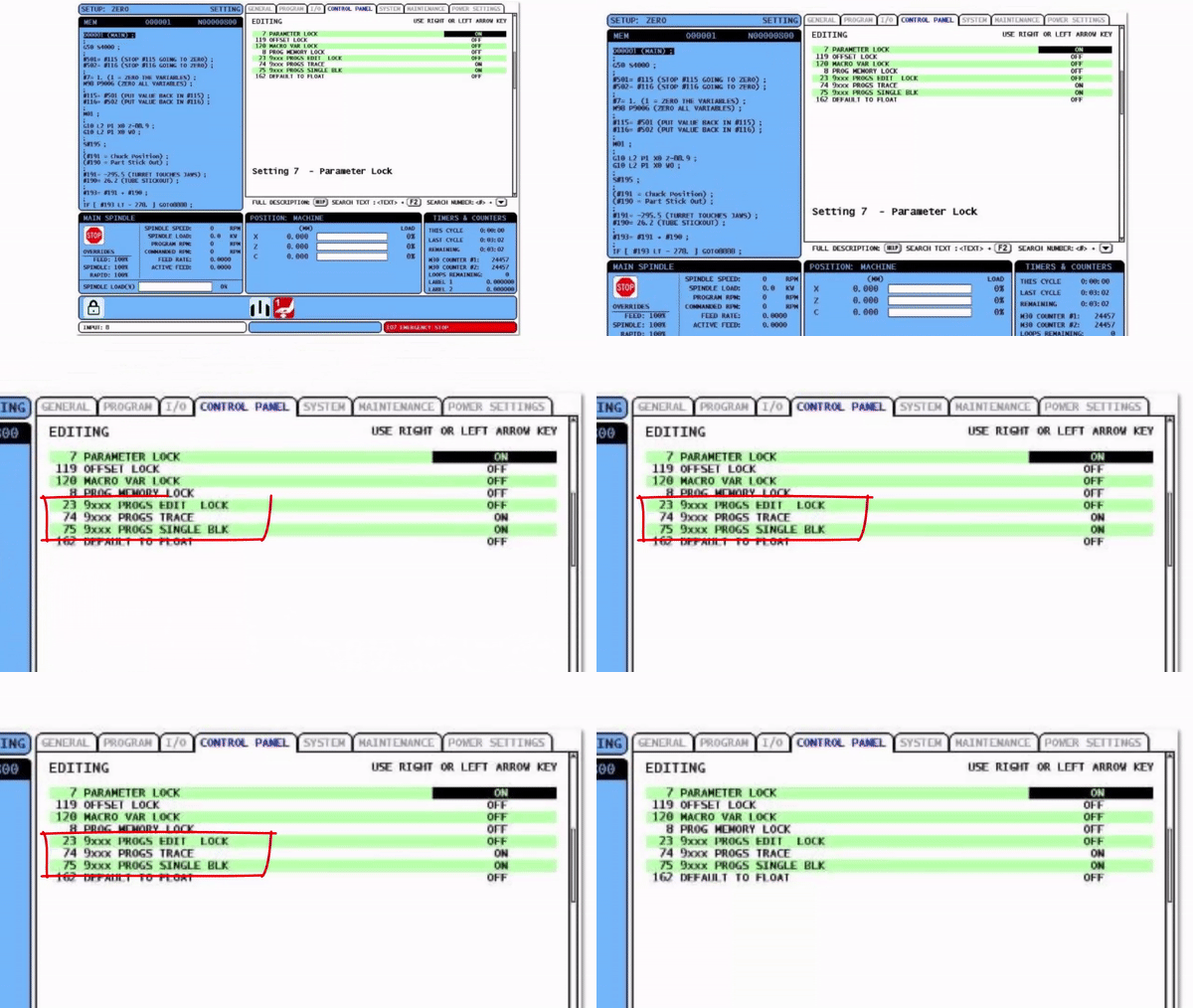
In your parameters you can alter a setting so that 9000 programs can’t be viewed or edited. So no one gets to tinker with your precious code. Below is Haas but you can do it on any control.

Welcome to the grown up world of macro because now you can make an M code that an operator can freely use but never access or alter. So to him it’s just a regular M code.

Oh don’t forget to tell him what it does otherwise he’ll never be arsed to use it.

You may well ask why can you do this with M codes and G codes. Well with M codes that’s really all you can do.

Let me explain….

With a G Code Alias………

You can add parameters. You know like when you use a G81 drilling cycle.

G81 calls a program that drills holes. You control the depth and feed etc with parameters.

Once you call a G81 it knows all about drilling holes. Like when it gets to the bottom it has to get the hell out of there.

G81 Z-20. R1. F100

  • G81 calls the cycle
  • Z-20. is the depth
  • R1. is the point to rapid to
  • F100. is the feedrate

The Z the R and the F are the parameters that pass into the program.

With an M Code Alias………

None of the above. It’s just an M code. Very useful I must say but you can’t pass parameters to it.

Toolchange (Fanuc Controls)

Ever worked on a machine where you have to write extra code to stop the spindle and take the tool up to zero before you can tool change?

Well that’s what M6 does, just tool change.

What most machines do is use an alias for M6.

So it’s not really M6?

Nope…..

M6 uses an alias. So in your parameters you make M6 access a 9000 program. That way you can put any old bollocks in the 9000 program.

When you subsequently use M6 it goes into this program which contains everything you could ever want for a tool-change.

  • Stop spindle
  • Turn off coolant
  • Return Z to zero
  • Feed the dog
  • Change the tool

And all with just an M6.

If you have one of these old machines you could make your own alias.

G Code Alias Passing Parameters?

This is where it gets clever and it gets complicated.

But……

You have me to hold your hand.

OK so you set G181 to access program O9010.

G181 A50. C20. Z-10.

This G181 would pass the values of A, C and Z through to program 9010

9010 would then use the values to do it’s business.

Mmmmm how does that work?

These guys below are know as the macro variable gnomes and each one has his own letter and his own macro variable.

G Code Alias

If you think I’m joking then go into your programming department and ask them. Say you want to learn about the macro variable gnomes.

It took me ages to do those stupid fuckin gnomes. Then I realized it wasn’t even funny but I couldn’t bear to get rid of them.

Below is a table that shows the corresponding variable for each letter. Forget the fuckin gnomes, it’s just a failed experiment. Let it go.

What this means is that if you put a value in A it will register in #1 and if you put a value in Z it will register in #26.

Then in your 9000 series programme it can use those values. It’s like a secret way to get information into your macro programme.

First of all put 181 in parameter 91.

G Code Alias


This means that G181 would call programme O9010.

Lets create a drilling programme the same s G81  we will call it G181.

It’s no different to G81 but it will demonstrate the use of Alias.

In other words it’s completely fuckin useless but at least I’ll get my point across. Oh yes, and stop picking fault with every bloody thing I do

G181 Z-20. R1. F200.

The G181 above will call O9010 and pass the values for Z, R and F into it.

#26 (Z)
#18 (R)
#9  (F)

Remember The List

G Code Alias

This is how O9010 Looks

O9010 (My Drilling Cycle)
G0 Z#18 
G1 Z#26 F#9
G0 Z#18
M99

Explanation

G181 Z-20. R1. F200.

O9010 (My Drilling Cycle Linked to G181)
G0 Z#18
#18 is the value passed from the letter R
R had a value of 1 so #18 is assigned the value 1
The machine will rapid to Z1.

G1 Z#26 F#9
#26 is the value passed from Z
Z had a value of -20. therefore #26 is assigned the value -20
Machine will feed to Z-20.
#9 is the value passed from the letter F
F had a value of 200 so #9 is assigned the value of 200
Machine will use a feed-rate of 200 mm per minute.

G0 Z#18 
#18 is the value passed from the letter R.
R had a value of 1 so #18 is assigned the value 1
Machine will rapid back to Z1.

M99

Don’t you just love all this shit?

This is Only the Tip of The Iceberg

See this post for grown up Macro programming

Thanks for watching and reading

If you have been affected by any of the issues in this post or need CNC Counselling then contact me.

Siemens 828 840 Sinumerik Training

Or call us 

If you want to learn to programme CNC Milling Machines

Look no further Contact CNC Training Centre


Adding a Fourth Axis or Indexer to your CNC

Category : Useful Stuff

Fourth Axis or Indexer?

When we talk about a fourth axis it means that we have four simultaneous axis X Y Z plus one other.

That means you can move them all together (the moves are simultaneous) and they are all timed together.

It’s a bit like trying to pick your nose and scratch your arse at the same time. You can get mixed up and poke your eye out.

CNC Machines are much better at this kind of stuff than we are.

Below is what happens when you program an X Y Z and C (rotary axis) move in one block of code.Fourth Axis

The one below is on a lathe so the Z works  the same as the X above.

In this program it’s just a Z C move or on a CNC Milling Machine it would be X C

Fourth Axis

Simultaneous

In the above example just the two axis (Z and rotary) are simultaneous..

If your machine has a simultaneous fourth axis, sometimes known as a full fourth axis.

On the position display you will see X Y Z but you will also see C (sometimes A or B I’ll explain later)

A full A B or C axis will be programmable in .001 degrees. That’s one thousandth of a degree (very small).

Typically G0 C185.326 rotate to 185.326 degrees

If a machine has an indexer and not a full fourth axis it normally won’t be shown on the position display.

Another thing to note about a full fourth axis is that it doesn’t stop at 360 degrees and start again at zero.

Angle wise 0 and 360 are the same but if you are talking simultaneous then it’s continuous.

Are you confused?

This is my pet goat his name is Beelzebub I named him after a famous politician.

Let me explain. In the example above (the fourth axis example, not my goat) you want the fourth axis to rotate more than once.

You programme C1440. which is 360 x 4 and it turns four times and the other axis works simultaneously.

So if the other axis (X) is moving 60mm. For each turn it moves 15mm. Just like a 15mm pitch thread.

Ok you get it now? Good. Very good. Just when I am starting to loose my fuckin patience with you.

The number of times I have to beat my students with sticks these days is getting more n more.

So What’s an Indexer

When we talk about an indexer on a CNC machine this means we have a rotating axis but we can only move it to a position. This can be 1 degree or .1 degree depending on the machine tool.

Whilst these are really useful you can’t do all that clever shit that you see above. So don’t get confused especially if you are footing the bill for a new or second hand machine.

Check the minimum angle you can index. If you have a part and it has holes at 10.5 degrees and your indexer is one degree increments then you’re knackered (or fucked but I have decided not to swear in these articles anymore).

You could be disappointed. “Sold a pup” as my mother used to say. I”l have to ask her what the fuck that means.

Don’t you just love them. I know they’re little portable shit machines but soo cute. Make lovely Christmas gifts.

Not on Linkedin though for fuck sake. Anyway enough gratuitous crap.

Retro Fourth Axis

Retro, a bit like sick and gay, this word has a totally different meaning to an old guy like me.

Political correctness to me means voting for the correct political party.

Now with regards to an indexer retro means it’s added on, like sticking a spoiler on your old Mini Metro.

What retro doesn’t mean, is wearing your dad’s old Parker Jacket and thinking you look cool when you actually look like a prick.

Anyway when you add an indexer to an existing machine you control it by a dedicated M code from the CNC Machine.

Your indexer will have it’s own little control system and programme. This programme will be a series of index moves probably followed by clamp and unclamp command.

The machine will send an M code to the indexer and won’t continue until it gets a signal back from your indexer saying it has completed whatever it is doing.

Now your CNC machine doesn’t give a flying shit what the indexer is doing, but it won’t carry on until it gets the signal back saying it’s complete. It’s like wall papering the hall through the letterbox, unless of course you are a gynaecologist.

You do have to be careful with all this stuff but it’s a relatively cheap way to get a programmable indexer.

Haas Fourth Axis

Haas machines come really well equipped and it’s usually relatively cheap to add a full forth axis years after you bought the machine.

After all they used make the bloody things, before they made CNC machines, I think.

They do a great range of add on bits n pieces.

Extras

This is all stuff to consider when you buy a CNC machine new. It can be really expensive to add at a later date as an extra. So bite the bullet, grasp the nettle and get one with your new machine. Give them my name so I get a fat commission.


Simple As ABC

A rotary axis can be called A B or C. This will depend on which axis it runs through.

On a vertical machining centre like this one the centre of the fourth axis runs along the X axis so it’s called an A axis

Fourth Axis

If it runs through Y it’s called a B axis. And Z well……. try n guess.

Full Fourth Axis Useful or Just Bullshit

In the real world there aren’t actually loads of jobs that need a full simultaneous fourth axis. Radial slots maybe radial engraving.

When you start talking about indexing to angles and just doing stuff, well there are loads and loads of uses. For example with a square part you can get all around it just by indexing so your part can come off complete.

Leave Your Fourth Axis Setup

Don’t forget to set your fourth axis as far to the right as you can so you don’t have to keep taking it off.

You should consider a base plate That way you can mount your indexer outside the machine stroke.

By mounting your indexer I don’t mean trying to shag it by the way.

Taking a fourth axis  off and on can be a real pain the arse.

Also don’t forget to use a G10 to store the work offset. If you don’t know how to use G10 then be ashamed of yourself and read this.

Add an Indexer or Fourth Axis

Adding an indexer or fourth axis to your small CNC Machine will increase capacity and allow you to rotate parts to get to areas you didn’t even know were there.

Here’s a free advert for someone

Surface AreaFourth Axis

If you consider the long cube on the axis above. You actually have four faces so it can be a lot of surface area when you add it up.

A lot of people make these cubes themselves and it can save money like baking your own cakes or performing your own keyhole surgery.

Thanks

Congratulations you are the first person to get to the end of one of my articles without being bored shitless.

If you feel you have been affected by any of the issues raised in this post or need CNC Counselling then contact me.

If you want to learn to programme CNC Milling Machines

Siemens 840D Sinumerik training

Look no further Contact CNC Training Centre


CNC Programming Basics Letter O Number Zero

CNC Programming Basics Letter O Number Zero

CNC Programming Basics, in my very early days of CNC I got to do quite a lot of work for Hitachi Seiki the Japanese machine tool maker that unfortunately no longer exist.

CNC Programming Basics

Many of their machines are still around and running. I was fortunate enough to be trained by a Japanese engineer who focused on the CNC programming basics.

The control was called Seicos which I think was based on the Fanuc control which Hitachi made themselves.


Anyway they had an equivalent of the Fanuc FAPT which was an automatic programming system.

It was the dogs bollocks of the day.

CNC Programming Basics

You could do maths on the fly with this control which I recon is a great idea.

Maths On The Fly


You could input say 8/25.4 then when you pressed enter, it would calculate the answer and input it for you. Lots of software like Fusion 360 do this today.

A couple of times I read a radius from a drawing say 15 for example and I would input 30 for the diameter. Every time he would stop me and say “no no wrong” (sorry I can’t do a Japanese accent).

He would insist that I input 15 x 2 and then press enter.

I didn’t think too much about it at the time. Over the years the penny has dropped as to the significance of this lesson.

CNC Training

When I am training people now I always say that you must input exactly what you see.

Roy Walker has a Catchphrase “Say What You See”  I just love this show. I suggest you watch it now because this article gets more and more boring as it goes on.

Anyway

So if you input exactly what you see you will make less errors.

“Say What You See”

“Say What You See”

For example if I had worked it out that 15 x 2=29 or I made a typing error then I would have been in trouble.

So at what point do you decide that you will use a calculator?

What he was teaching me was, wherever possible make the machine do the work.

CNC Programming Basics


Taking this to its logical conclusion the way you programme from a drawing is really important and it is all part of CNC Programming Basics.

  • Make the datum wherever possible the same as the drawing.
  • If the drawing has several datum’s you could also have several datum’s.
  • If holes are dimensioned 15.865 apart and you have 4 holes don’t add it up programme it as incremental.
  • If you have polar programming (G16) on your machine and the drawing is dimensioned that way, with angles and rads, then use polar.
  • Here is a post on how to use G16

It’s Right there in Front of You

What this means is that when you look at the programme and you look at the drawing it is really easy to understand what you are doing. Remember what I have said in many posts before.

If you are the programmer the setter is your customer.

If you are the setter then the operator is your customer.

When someone else picks up your work they should easily be able to see what you are up to.

Unless your one of those assholes that really doesn’t want them to understand.

  • Read the drawing and you can see the same figures as the programme.
  • Check out the datum and it’s the same as the drawing.

We always emphasise this when we are training programmers.


The Point

Let me now get to the real point of this article this Japanese guy would never allow me to say G O as in letter O. He would insist on me saying G zero. If you think about the translation here, the only reason that we get the two mixed up is because they look the same. I would imagine to him it seemed totally wrong.

The thing is it is totally wrong.

CNC Programming Basics


CNC Programming Basics

If you place a letter O accidentally in your code instead of a number zero when you read it into your machine it will start a new programme as soon as it sees the letter O.

So you will end up where you and your poor machine are both very confused.

The letter O has only one use in a CNC programme it precedes the programme number to begin a programme (see below). The comments in brackets are totally ignored by the control and therefore you can put what you like while you are protected by the brackets.

By the way if you want to use foul language or childish rude comments them please make sure they are parenthesised. I often do this myself.

O0001 (G81 DEMO)
G21 G90 G40
T01 M06 (20.0 MM DIA X 90 POINT SPOT DRILL)
G90 G0 G54 X12.64 Y88.0 S2546
G43 H01 Z15.0 M8
G0 Z100.

Where Else Can you Use The Letter O?

Sorry I lied to you. There are other uses for the letter O.

I only lied to protect you as a beginner.

What are they? Let me know

Please contact me if you require:

  • CNC programming training.
  • Want to learn CNC programming.
  • Fanuc control training.
  • Yasnac programming training.
  • Any type of CNC course.
  • Fanuc training courses
  • CNC lathe training
  • CNC Vertical Machining Centre training

Services offered at CNC Training Centre

Edgecam training.

Classroom programmer training.

Onsite CNC Machine Training.

CNC and Training on all controls and machines.

Mazak Training Fanuc Training

Don’t forget we offer training on all types of Mazak Machines and all Fanuc Controls 6m to 31i Oi old to young.


Maximum Wear Offset Fanuc Parameter 5013 5014

Category : Fanuc Parameters

Messing With Parameters Can Be Fatal!!!!!

Maximum Wear Offset Fanuc Parameter.

To change parameters you need to go to the setting screen in MDI. Now put a 1 in the parameter write box.

Maximum Wear Offset Fanuc Parameter

Today I want to talk about safety. (you know it’s that boring shit at the front of your machine manual that nobody reads).

Anyway in your offset table, if your machine is less than 30 years old you will have a table for wear and a table for geometry.Maximum Wear Offset Fanuc Parameter

Well when Mr Fanuc first thought of this, his idea was that instead of keep altering the big number in the Geometry you would have this small wear adjustment. He also gave us the input plus key so you wouldn’t need to do any arithmetic.

The machine would add the wear and geometry together and bang you would end up with a correct part. Newer controls even display the result for you.

See Below Cool!!!!

Maximum Wear Offset Fanuc Parameter

Safety

Always use the wear and never alter the big geometry figure unless you are resetting the tool.

The blue W or G on the left hand side can be a bit confusing. Nothing to do with G codes or incremental movements on a CNC Lathe

G stands for geometry and (yes you guessed it) W stands for wear.


Maximum Wear Offset Fanuc Parameter

Let’s get on with it.

You would think I would be bored by now and off to write another rock tune that no one will ever buy or listen to, but I’m not.

These articles are about parameters and just generally fucking them up so your machine is crippled.

To Be Real Super Safe

No you don’t need to put condoms on all of your fingers or anything like that.

There is a parameter that can limit the amount you can add to the wear and another that controls the maximum this can reach.

If you think about this. Imagine if you put the apprentice on the machine and you want to be sure he doesn’t start a nuclear war with a foreign dictator.

Oh by the way there’s not a parameter for that.

What you could do is teach him to use wear and not geometry. When the wear reaches the maximum the machine will give an alarm. You will then know it’s time to look at the tool.

Also he couldn’t input a massive amount and crash the machine.

Let’s be honest here, if that wear figure is high something is obviously wrong and you need to re- measure the tool or chuck it in the dustbin.

So here is the parameter.

Maximum Wear Offset Fanuc Parameter


Maximum Wear Offset Fanuc Parameter

The above parameter (5014) stops you from altering the wear offset by anymore than .1 at a time (don’t be greedy).

Maximum Wear Offset Fanuc Parameter

The above parameter (5013) means that the maximum amount you could have in the wear offset is .3

Don’t panic when you get one of these.

Maximum Wear Offset Fanuc Parameter

It just means you broke your own rule when you promised never to exceed .1 when you alter your tool wear.

I hope you have enjoyed this parameter as much as I have (in which case we have both been very bored)

Other Parameters Of Interest

3203 Clear MDI Screen

3204 Unlock Program 9000 to 9999 and 8000 to 8999 to Edit

3401 Calculator Type Decimal Point or Integer

6005 Allows the Use of Local Subroutines (Newer Control)

6050-6059  Allows you to Call a 9000 series Program with a G Code

6080-6089 Allows you to Call a 9000 series Program with An M Code

That’s it away you go.

Oh just one other thing before you go off and cripple your machine forever.

Do yourself a favour take a picture of the screen before you change your parameter.

If you aint got a camera then you must have a piece of paper so write it down.

(Oh and get a camera they are very useful you can take pictures of your arse and send them to your mates)

Even better back everything up.

Thanks

If you have been affected by any of the issues in this post or need CNC Counselling then contact me.

If you want to learn to program CNC Milling Machines

Look no further Contact CNC Training Centre


How to Limit Wear Offset Input on Haas Machines

Category : Haas Settings

Haas Limit Wear Offset Input

This article tells you how to limit wear offset input on your Haas Machine.

limit wear offset

Collisions should be avoided at all costs on a CNC machine, so anything you can do to prevent them has got to be a good thing.

There are many things you can do, like paying careful attention to the way you prove out your program.

When run a programme that has already been proven, you know the actual CNC code is fine.

limit wear offset

So you have two things to worry about.

  1. Is the WORK SHIFT or WORK OFFSET correct?
  2. Are the TOOL OFFSETS correct?

These are the two things that you control and they link the programme to the machine.

It would make sense therefore to check each tool change. Check the point where it first approaches the workpiece.

Once a programme is running we only need to go into our prove out mentality when we change the programme or the tool wear offset.

When we adjust the tool offset we can either adjust the Geometry or the Wear. Now it’s always best not to touch the Geometry. That’s because it’s a big number and big numbers can hurt you.

Lets say this number was 200.986 and you wanted to move it by 0.116

Not too difficult but it would be quite easy to alter it by  a large amount and not even notice.

Then you could be in trouble.

Now if you always use the WEAR you know it’s always going to be a small amount. So if you see a large amount in the wear column you can go into a mad panic.

What’s The Point of All This Where’s He Going?

So if you always use the WEAR and not the GEOMETRY you’ll be ok. Unless of course you were stupid enough to put a big number in the WEAR

or…….

Against my advice you alter the GEOMETRY.

Help Is At Hand (limit wear offset)

On a Haas Machine you can limit wear offset amount in a your settings.

It still lets you do it but gives you a sarcastic little warning.

Press this button

limit wear offset

Sorry it’s a dirty grubby button but it’s the only one I have (welcome to the real world)

limit wear offset

Type into setting 142 the maximum amount you want to limit wear offset input by.

Now if you try n exceed the dose, this is what you get.

limit wear offset

Note

This limits the amount you can add to your offset not the total amount of the offset.

Thanks for watching and reading

If you have been affected by any of the issues in this post or need CNC Counselling then contact me.

We really love you but honestly we don’t give a shit if you break your machine. If you do, make sure you YouTube it. You could make a shit loads of money from the video.

Oh yea we do CNC Training too, not to mention Classroom Training.

Or call us

If you want to learn to program CNC Milling Machines

Look no further Contact CNC Training Centre


Careers in CNC

View all current vacancies in CNC

Click here

Call David: 07834 858 407