We all know that programming can be complicated. So let me explain to you how it all works. This article explains the real meaning of Modal and non modal G codes.
Modal means that once a command is issued it stays in the control.
How Can you Actually Use This?
If you issue a G0 or G00 command the machine is in rapid and you do not need to re-state it.
Rapid means all motors are flat out, like a teenager in a Ferrari.
Every move from then on will be a rapid move unless you tell it otherwise. The G code that changes it must be in the same group. For example G0 G1 G2 and G3 are all in the same group a bit like The Beatles used to be.
The other day I was talking to a “young person” who hadn’t even heard of the Beatles. I mean fuckin hell, am I really really old or are they doomed to be forgotten?
This is a video explaining cutter compensation in CNC programming.
You will come across various terms to describe this such as:
Tool cutter comp.
CNC cutter comp.
G41 G42 cutter compensation.
Cutter diameter compensation.
Cutter radius compensation.
Heidenhain RL RR.
Cutter compensation is referred to as cutter diameter compensation and cutter radius compensation
Haas cutter compensation, Fanuc cutter compensation and Mazak cutter compensation all work in the same way.
Although Heidenhain cutter compensation or Heidenhain cutter comp looks different. In the programme it functions in exactly the same way.
In the parameters or settings of your control you can set up your system to use the radius or the diameter of your cutting tool.
This means that when you input the data for your cutting tool in your offset table you can use the diameter or the radius of the tool. This depends on your settings.
When people talk about cutter compensation G code they may say “cutter comp G code” it’s often shortened.
(Cutter compensation G code)
The G codes used in this video are:
G41 cutter compensation left
G42 cutter compensation right
G40 G code to cancel cutter compensation
This Video shows you :
How to program G41.
How to program G42.
CNC cutter compensation examples.
Cutter compensation Heidenhain style.
Heidenhain RL RR.
We always recommend that you climb mill so you will be using G41 most of the time.
Milling the outside of a square using G41.
Milling the inside of a square using G41.
Milling the inside of a square using G42 (should you want to conventional mill).
Milling the outside of a square using G42 (should you want to conventional mill)
The rules when using compensation on a CNC Milling machine.
This is simple on a square sided figure or a simple radius. Anything more complex and it’s a nightmare.
I just heard some smart arse say “Ah well my CAD system takes care of that”.
So it should my friend but, and there is a but:
What will you do when your cutter wears?
What if you want to use a different size cutter?
The cutter may not run true.
What if the cutter is not exactly size?
In the old days of paper tape and Corned Beef we as programmers would write several programmes.
This was so that we could re-grind the milling cutters in fixed increments. A different programme could be used each time the tool was changed.
Sorry I can’t talk about this much longer as I still have the nightmares (mainly about corned beef sandwiches).
Anyway enough of that. So when we machine our first profile we can add some on to the tool radius in the offset file. When we check the part we can adjust the offset and re-cut the profile to achieve an accurate result.
The Rules:
Shape must be continuous and consistent.
You can’t cut along a line and then go back along it.
It’s important to allow more than the tool radius when entering tool compensation. The same applies when you come out of tool compensation.
Internal corner radii and steps must be greater than the tool radius.
Always allow more than the radius because when you adjust it it may be larger than the actual tool you are using.
Don’t ask
For example if you have a 12mm endmill but you have .2mm in the wear compensation. The machine thinks that the tool is 12.4mm in diameter.
You can’t do this in cutter comp:
You would have to apply one cut in G41 and cancel with G40 then do another cut in G42 and cancel with G40:
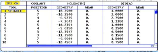
I recently got to train someone on one of these, a Webster & Bennett with Fanuc 10t Control.
It’s what I crudely call a big bastard. But bastard it is not, it can definitely machine some big shit
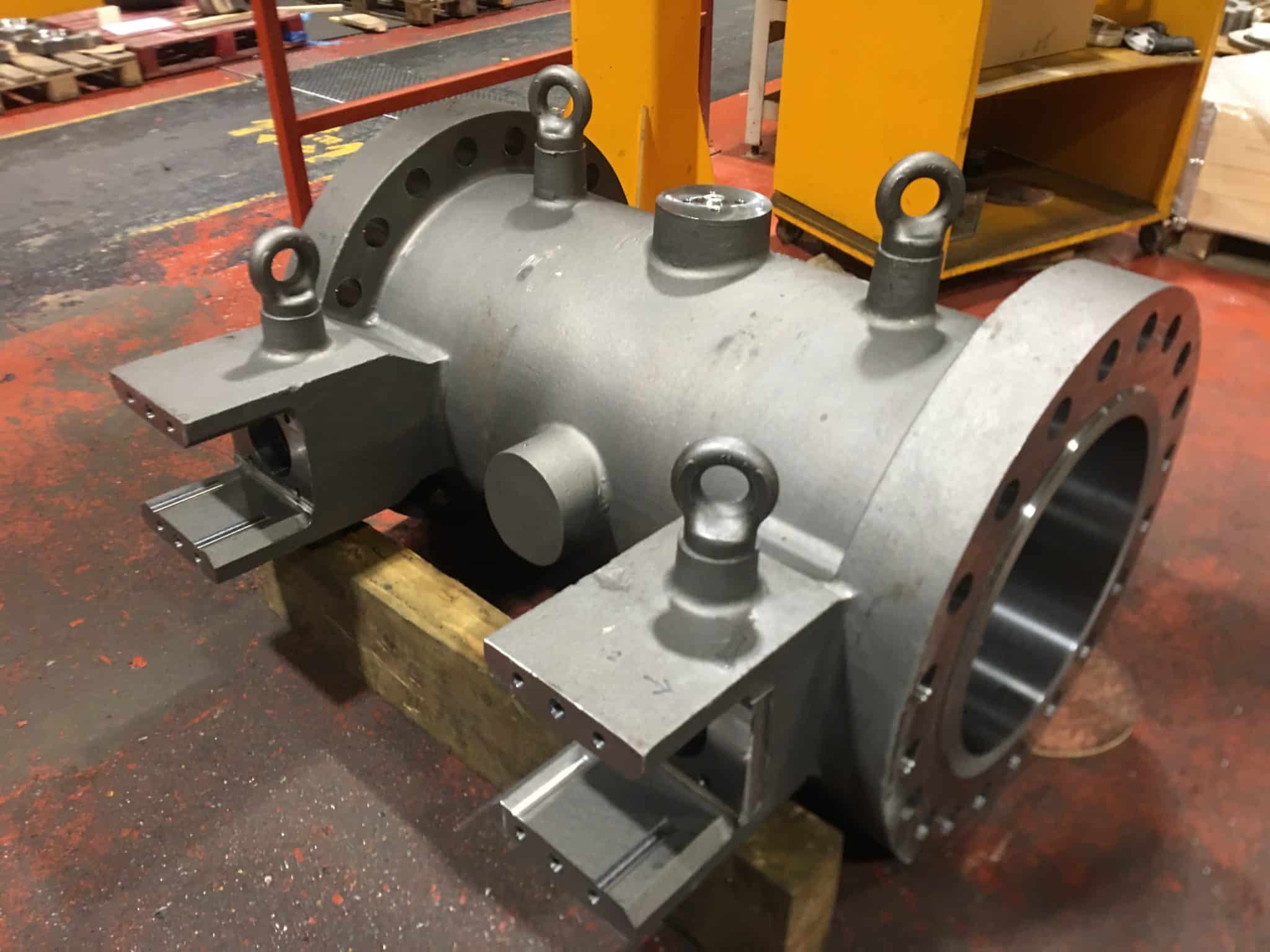
Like this monster.
Don’t ask me what it is or I would have to kill you. Joking aside I think it’s a water valve. Beware these jacuzzis use a lot of water,
The machine is a Webster & Bennett vertical borer and I think the Fanuc 10t control was possibly a retro fit.
When these start whizzing around even a few RPM it can scare the living shit out of even the most seasoned engineer. And me, well I,m more seasoned than a piece of Nando’s chicken.
G50 on a Webster & Bennett Your Best Friend
Anyway joking aside your best buddy now is definitely G50 get this wrong and it’s fuckin world war three.
Imagine the scenario, you program G96 S180 M3. Spin at 180m/min. Not too fast but…. what if the tool is sat in the middle of the part.
Machine says “come on lads happy days foot to the floor flat out joy riding” and it fucks off like two teenage boys in a stolen Lamborghini.
So without aG50, or the wrong speed, this beast will accelerate to it’s maximum rpm.
Oh and did I Mention it’s harder to stop than a P & O Criuise Ship with 4000 obese pensioners on board?
Here are ten things you might not know about Fanuc sub programs,
Fanuc CNC controls are the most common controls in the world so it might be useful to have a good understanding of how sub programs are called and used.
(1) You Can Call a Sub Program By Name.
Yes you heard it here the program can be called by it’s name or it’s number. When calling by name don’t use the P.
Just put the name of the program in these things <> with an M98 and your away.
M98<ALBERT>
The only problem with this is that the syntax needs to be spot on so if you have got complicated names for your your sub routines then you might be in the shit.
I always call mine names like ALBERT that are easy to remember.
(2) You can use internal sub routines on a Fanuc Control.
Some people call these local sub programs. It just means it’s tagged on the end of your program which makes them nice n easy to look after. A bit like a pet Goldfish or a pet fly.
I bought mine from the local pet store. I asked the assistant if he sold pet flies and he said no. I said “well there are loads in the window”.
Anyway he sold me one (£15) his name is Paul
This is not him this is Steve.
Internal Sub-Routines
By typing M98 Q500 your control will look for N500 within your current program. This is great because you can add the sub programs to the end of your main program. Don’t forget to leave big gaps so you can clearly see where and what they are. Oh and mind your P’s and Q’s.
Now I’ll warn you that it’s not a simple process but if you get into the habit of using it you’ll never leave home without it.
I am definitely not going to rant on and on about why all these simple procedures were not introduced years and years ago. Why has the editing on CNC controls generally been so shit over the years?
I am also not going to rant and and whinge about how fuckin complicated it all is.
I mean bloody hell all I want is to take this shit here and join it to the end of this shit here.
I’m not asking for an “X Factor Audition Here” (Simon if you are reading this my contact details are above) I only write this crap to try and make some money, my really passion is singing and exotic dancing in my underwear. I really want this Simon, just one chance is all I need.