This is part of a series of articles, CNC For Beginners.
The order of your code in one block does not matter from the computer’s point of view (see below).
The computer gobbles up a line or block of code and then makes sense of it. you programme G90 G0 X50. Y50. Z50. all the axis will move together so G90 G0 Z50. Y50. X50. would be exactly the same. I just jumbled it up, not to confuse you, just to show you that it does not matter.
O0001 (G81 DEMO) (PROGRAMMER PETER ANDRE) G21 G90 G40 (G90 G40 G21) Works the same
T01 M06 (20.0 MM DIA X 90 POINT SPOT DRILL) (M06 T01) Works the same
G90 G0 G54 X12.64 Y88.0 S2546 M3 (S2546 M3 G90 G0 G54 X12.64 Y88.0) Works the same
However it is best to keep the order the same. Create your own convention and stick to it. G90 G0 G54 X12.64 Y88.0 S2546 M3
If you programme as above you will get used to the order and your programmes will be easier to read.
At a customers recently I got really frustrated by the inconsistency of the program. I did the only thing my upbringing has taught me to do.
Headbutt the nearest object.
Consistency (CNC For Beginners)
G90 G0 G54 X12.64 Y88.0 S2546 M3
So you could begin with absolute or incremental (G90 G91).
Then rapid or feed (G0 or G1).
Then G54 (G55 G56…..) work offset.
Then X Y Z not Z Y X.
Then Speed S2546
Then turn on spindle M3
For example if the speed was always at the end of this line you would notice straight away if it was missing
It’s like reading telling the time we learn to recognise patterns.
So although the running order does not matter, in terms of the way the programme runs, it is important from a visual point of view.
Try to make your programmes consistent and to a regular pattern. Anyone using your programmes, including you, will find them easy to read and to fault find.
Remember if you are a programmer then the machinist, setters and operators are your customers so try and imagine the programmes from their perspective.
On these controls you don’t get any choice in the way the code is set out so you don’t need to worry. In fact you wasted your time reading this article.
Rules (CNC For Beginners)
I often say to customers that I work with that it does not matter how you do a lot of these things but you must have a consistent approach.
A good idea is to write a standard operating procedure (SOP) this would document exactly how the running order will be. If you are using CAD/CAM you will need to get into your post processor and make sure it outputs the code in accordance with your SOP.
Even down to leading zeros and training zeros do you programme G0 or G00 do you programme X.2 or X0.2. I know what I prefer because I hate wasting space (I am old school when memory space was sparse). It really does not matter but you must have a consistent approach and if you are not the only programmer, meet with your colleagues and come up with a plan.
If you don’t for example programme X50. Y60. Z80. in that order there is a good chance that you will alter the wrong figure and end up with two X figures or two Y figures.
Standardisation will mean less confusion and it will reduce errors.
Haas Setting 103, I think this is so cool and is typical Haas. Try changing setting 103, this makes the green CYCLE START only work when it is held in, a really good way to prove out a programmes. Can’t wait to try this.
The settings page on the Haas control is very exciting, as well as Haas Setting 103, you will find a myriad of exciting things that will change the behaviour of your Haas control. Read the manual very carefully before embarking on this journey.
This is where you can turn on your programme restart which is probably the single most innovative thing on this control, it always amazes and annoys me in equal measure when I see people not using it.
Setting 15 is a great one to use too.
This checks that when you programme your tool length compensation G43 Z3. H01, that this tool length offset agrees with the previous tool call-out (M06 T01).
So if for example you programmed M06 T02 it would throw up an alarm telling you that the H and the T code did not agree.
I am sure you must have changed a tool position and forgot to change the tool length offset number (the H number). Easy done.
It’s what makes us get of bed I often lay awake at night thinking about what you can do with these setting. Mmmm…..
The settings are designed to be changed by the user, so don’t worry too much about changing them.
It’s a good idea to make a note of these settings before and after. Maybe take a picture if you can’t be arsed to learn how to do a screen shot
It’s only when you start getting into changing parameters that you really have to think “am I ready for this Leap Of Faith”
But nevertheless there again there is some real interesting stuff here, another article maybe? Anyway have fun with this and come back and tell us how you got on.
We will get to Roundness but first I am going to ramble on, because I always do, but I often think of when I worked with my dad many years ago.
My dad was a brilliant old school engineer and he worked for Alfred Herberts from boy to man, apart from a brief period in the RAF. In its day Alfred Herberts was the biggest and most successful machine tool builder in the world.
My dad finally lost his job and had his pension robbed when AH finally went bust. I was running an engineering company so it seemed obvious to have him working with me.
My dad’s claim to fame was that he worked the first Cri Dan machine. This was an amazing innovative machine that could hold its own, until fairly recently, against a CNC lathe for high-speed threading. There are still a few about now.
My dad often joked that he could offhand grind a 1/16 of an inch drill and read a steel rule to a thousandth of an inch which I am sure was bullshit although I would never dare to say.
I remember we were trying to turn and bore some motor bodies on a Mori Seiki lathe and we could not get them round. Anyway he told me to weld up some jaws so that they would fully envelop the part.
Basically the part had nowhere to go. It was like a big collet and it worked.
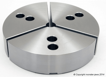
They are nowadays called pie jaws which you can buy from your local tool supplier or from Gregg’s as part of a meal deal
Our inexperienced inspector was trying to measure roundness with a micrometer which I am sure you all know cannot be done.
An argument ensued and profanities were exchanged. We ended up buying a Talyrond roundness checker which is the correct tool for the job.
As it happens the same thing cropped up in a customer’s only a few months back. I caught them trying to measure roundness with a micrometer. Back to basics again.
These days I have a much better way to prove my point than shouting and swearing. Please note I still make my point by shouting and swearing which us less intelligent folk always tend to do.
This method is cheap and free of all profanity it cost 50 pence to be precise.
I threw them a 50p piece (UK Currency) or even a 20p for the real cheapskates. “Is that round” was my question. They laughed.
.
“Here is a micrometer now check it for roundness”.
You’d need one bigger than this.
Mmm it’s dead round when you check it with a micrometer.
The smart arses amongst you will know that a 50p piece is an “equilateral curve heptagon“. And it measures the same across any two points you care to choose. It proves that you can’t measure roundness with a micrometer. Unless of course you think a 50p is round and the earth is flat.
Oh yea and if you were wondering “why the fuck would you make it that shape?” Just try and put a regular seven sided coin in a slot machine.
The Plug
I won’t be teaching you about roundness on my training courses ,that would be silly cos you already know. If you are interested in learning basic CNC Programming for a Lathe or Milling Machine look no further.
The New CNC Training Classes focus very much on the basics giving a solid understanding of the nuts and bolts of CNC programming on an ISO Fanuc Haas type control.
CNC lathe tool nose radius compensation, I think that sometimes in life we get off to a bad start with things. I know when I was at school I was convinced that I was useless at French, Physics and all sports.
I just got off to a bad start.
Getting stabbed with a javelin in the foot did not enthuse me with regards to sporting activities.
Oh and two of my close friends wanted to see if passing a high voltage though my body would give me special strengths a bit like Frankenstein. Needless to say it didn’t work and to this day I can’t watch those films.
So when you have a bad experience with something it just puts you off.
Maybe when you first tried to use G41 and G42 you got loads of ALARMS. Not to mention that nasty rash that you needed a three month course of antibiotics to clear.
We often find ways around our lack of knowledge or whatever.
I know when I was in France my mate always spoke English in a kind of French accent thinking they would know what he was on about. He would put an “a” at the end of each word.
He would say “doa youa knowa thea timea” and they would say “Va te faire foutre”
Here is the video (DON’T YOU DARE WATCH IT YET)
Sorry about the long intro but I have a record to sell as well.
If you liked this video, please don’t forget to subscribe to my YouTube channel by going to:CNC Training Centre
Anyway, Tool Nose Radius Compensation.
People find ways of programming without tool nose radius compensation.
It surprises me when people don’t use it and it is usually because they don’t understand the very simple rules.
Rules CNC Lathe tool nose radius Compensation
The daftest one being, don’t ask it to do the impossible.
So if you are machining a diameter of say 40mm and you move to a bigger diameter 40.5
If your tip radius is 0.8 the machine would alarms out.
You swear at the machine but unfortunately it’s you that’s being a prick. You can’t fit a .8 radius in that gap.
The same thing applies if you machine around a radius that is smaller than the tip radius.
The other common fault is knowing when and where to apply it. (A bit like lip gloss.)
Your shape needs to be one continuous path that does not go back on itself.
No reverse gear.
I always say “use it and get rid of it”.
You can’t just move on to another shape.
You need to cancel and then re apply.
If you don’t use compensation your parts are not really correct because you are frigging the figures. You naughty naughty boy.
CNC Lathe Tool Nose Radius Compensation
The other big problem is if you need to change the tip radius and you didn’t use tool nose radius compensation you would have to change the program.
Your program and part will simply be wrong without tool nose radius compensation that is unless you are only machining orthogonal lines. (Some of my readers will need to goggle that)
If your CAD system is not outputting tool nose radius compensation or cutter compensation in milling then you need to look at your post processor.
If you can’t do it get your software provider to help. Believe me they can all output this if they are set up correctly.
If you liked this video, please don’t forget to subscribe to my YouTube channel by going to:CNC Training Centre