G01 not GO1 Back to Basic CNC Programming
The letter O is only used for a programme number and a GOTO statement on a Fanuc Control. It’s important not to get it mixed up with the number Zero. So we should really say G zero one ( G01 not GO1 ).
So remember it’s G01 not GO1 (Zero not letter O)

A good solution is to miss it out where possible G1 not G01 etc.
This is part of a series of articles designed to cover basic CNC Programming.
When I first learnt to programme, before the First World War, I still remember how daunting the thick yellow Fanuc Manuals were. The Japanese were learning to speak English and we were learning to speak G Code.
Fanuc Manuals
Fanuc manuals are just like the yellow pages. A note here for you young people who might not know what yellow pages are (no it’s not like someone pissed on the photocopier)
Long before Google we had these thick yellow books and we used them to find stuff like if your mam needed to get the outside toilet unblocked or something.

None of this stuff was in the Fanuc manuals but you could easily get them mixed up cos they looked very similar.
I can honestly say when I was learning Basic CNC Programming I read the old 6M Fanuc manual from cover to cover. The Macro bit was just like another planet to me. Some things I had to read over and over again to understand.
Some of it was so badly written you kind of had to guess what they meant.

In the Beginning
Every now and then I used to go right back to the beginning and read the basic stuff again. Believe me, every time I would find something I didn’t know, mind you I didn’t know much then anyway.
Try it later and if it doesn’t work I’ll give you your money back.

Okay enough of this bullshit and verbiage let’s talk about G codes.
Geometric Code, that’s what the G stands for.
Useless information but anyway, now I’ve said it. Don’t tell your mates down the pub because you will probably bore them shitless.

I often begin my training courses by saying “you only need to know four G codes to programme a CNC, it really is that easy”
G0 G1 G2 G3
(Please smart arses don’t contact me.)
What that means is that you can get round any shape with straight lines G1 and circles G2 and G3. Oh and you need to quickly get to the part so use G0 rapid.
Yes and another note. You don’t need leading zeros.
G00 can be G0 (Never GO as in letter O)
G01 can be G1 (Never GO1 as in letter O)
G02 can be G2 (Never GO1 as in Letter O)
G03 can be G3 (Never GO1 as in letter O)
Read this if you want to know more.
Lets Get On with It
G00 or G0 commands a rapid move. That means the axis will be flat out. Maximum foot to the floor, shit off a stick as we say in the Midlands.
A common mistake with rapid moves is to assume that the axis will all move in a straight line like a bullet from a gun.

Not true. Because each axis is flat out one axis may arrive before the other. The rapid on your X axis could be slower than your Z. Anyway you get what I mean.
Why do I need to know this?
Easy because if something is in the way then you might hit it. That is if you assume the movement is a straight line.
Now lets see.
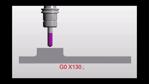
Move down in Z
G0 Z5.

Then a nice straight line G0 X130. Z-30.

But meanwhile in the real world

It’s obvious really.
Just think for a moment:

If both X and Z rapid motors ran at the same speed. Then each axis will move the same amount until one reaches its destination.
Looks like this.
Z has 30mm to move in total so they will both move 30mm. This will make a 45 degree line.
Ah but X is not finished yet. X will carry on and finish its move in a straight line.

If something is in the path of your rapid move you may need to programme your axis separately to be sure not to hit anything.
G00 X130. Z-30.
Could be:
G00 X130. ;
Z-30.;
Please don’t repeat the G00 (you know it will piss me off).
Now G01 ( G01 not GO1 )
G01 is a linear feed. It means feed in a straight line. Just like stretching a piece of string between two points. It can be just one axis or two simultaneous axis. You can even programme X Y and Z all in one line of code.
So this is what really separates a CNC from a manual machine. Remember how hard it was to machine an angle on a manual milling machine? Or a taper on a lathe.
You do?
Well on a CNC Machine we just programme the end point. It will then machine a straight line from it’s current position to the programmed point
If your machine was at X50. Y0 and you programmed a line
G01 X55. Y-200. ;
You would get an angle.
Ok what’s wrong in this picture?

Just to see if you are not a robot?
Yes congratulations but what is wrong with the line.
G01 X55. Y-200. ;
The Feed-rate
Yes with G01 you need a feed-rate. Don’t repeat the feed-rate, you only need another feed-rate when you want to change it.
G01 X55. Y-200. F100. ;
Don’t forget you can programme X Y and Z together and it will still be a straight line just like you tied a piece of string between the start and end point.
F100. means feed at 100mm per minute.
CNC Turning
On a manual lathe you would have to set up a compound slide to just machine an angle.

Mmm very skillful and I’m sure it’s loads of fun.
On a CNC Lathe this is just one line of code and some Basic CNC Programming!!
What About 3 Axis Rapid?
Yes you can programme 3 axis together in rapid move. It’s definitely the quickest way to get to the part.
G0 X50. Y20. Z3.
I would definitely advise using it but, and there always is one, just be real careful nothing is in the way. Don’t blame me I’ll just say I never met you.
Oh just one more thing as Columbo would say.

You could use a very high feed instead of a rapid move. That way you really would guarantee a straight line. I’ve never done this but it just came to me in a flash.
So there you have it G0 is rapid ( never GO letter O).
G1 is linear feed, remember G01 not GO1 (Not letter O)
Thank you for reading my article ( Basic CNC Programming G01 not GO1 )
Services offered at CNC Training Centre
Edgecam training.
Classroom programmer training.
Onsite CNC Machine Training.
CNC Training on all controls and machines.
Mazak Training Fanuc Training
Don’t forget we offer training on all types of Mazak Machines and all Fanuc Controls 6m to 31i Oi old to young.