Heidenhain Q parameter programming is very similar to Macro CNC Programming for Haas and Fanuc.
Once you have grasped the concept of parametric programming you will find Heidenhain Q parameter programming easy to figure out.
Suitable for Fanuc, Mazak and Haas Macro Programming Lathe and machining centre
Haas, Fanuc or similar controls (ISO Mazak).
Make sure you have the Macro option on your control, it’s a real disappointment when you get all excited about this only to find you don’t have the option. Remember if you have a touch probe you will almost definitely have Macro installed on your machine.
Good news is you can buy the option, it don’t come cheap so sit the boss down and make him a cup of tea before you ask.
CNC Macro Programming Training Courses
What Use Will it Be?
This is where CNC Programming gets really exciting, welcome to the turbo charged world of Macro Programming for Haas and Fanuc type controls. There is so much exciting shit you can do with this I really don’t know where to start.
Write your own canned cycle
Yes you always dreamed of having your own personal G code, you can’t call it like Bill’s G code or something but you may have G271 or something which is personal to you.
Say you wanted a drilling cycle that changed speed half way down a hole or some daft thing well now you can do it.
Make A Set of Similar Parts
Imagine you had a bunch of parts that were similar, maybe the same holes but in different positions or a similar shape.
You could write a parametric (Macro) programme that would be completely adjustable and would make them all instead of having to keep writing similar programmes.
You can build these programmes and add to them as you get better and better and your ideas flood in.
I always say to students to start simple and build on your experience. Just using Macro in its simplest form will inspire you to go on to do greater things.
Interrogate Your CNC Machine
You can get almost any information you want from the machine.
Spindle Speed.
Position.
Datum.
Tool Length.
What tool is in the spindle.
Put the machine into an alarm state when things go wrong like wrong data is input.
And loads more.
You can even modify this information and send it back.
Do Calculations
Simple trigonometry.
Calculate feeds and speeds.
Simple maths.
Input formula and get answers.
I’m getting really excited just telling you this. It means you can add all sorts of functionality to your machine that you didn’t have before.
What Skills Will I Learn
Basic use of variables
Creating simple Macro programmes
How system variables work
How to write probing Macros
Creating your own G Codes
Create alarms to make sure your Macro users behave
G0 G54 X0 Y0 (Rapid to X0 Y0 using G54) X50. Y50. (Still rapid still G54) Z10. (Don’t panic I know you still want rapid and G54)
Zero Return
When you first turn on your CNC Machine you would normally reference or Zero Return all the axis. The machine then knows where it is.
All machines will have a position display. This position display will have one set of figures normally called “MACHINE“. This is the machines position from zero return. So when the machine is at zero return this will read.
X 0.000 Y 0.000 Z 0.000
The “MACHINE” position tells us how far we are from the machine zero. We don’t use this once we have set our datums.
This is the position we need to write into the work offset page to tell the control where each datum is (G54 to G59)
What we do when we are setting (G54 to G59) is enter this position in the work offset page.
When we subsequently call this G code the machine will use this position as it’s datum.
On the screen above if you programmed G0 G54 X0 Y0 the machine would move -75. in X and –145.5 in Y. This is it’s new zero position. Every subsequent command will work from this datum.
Now Let’s Set The Work Offsets
What we do when we are setting the machines datums or Work Offsets is we tell the machine where our datum is from Zero Return.
In the above case the datum is 806.25 away from X Zero Return and 147.1 away from Y Zero Return. These will both be minus figures.
What about Z you say?
Well yes we need to do that also. The Z will be the distance from Zero return to the top of the work-piece.
So in the above case the distance from the spindle nose to the top of the work-piece is 530.570. Again this will be a minus figure.
So there you have it your work offset in X Y and Z.
This is how it looks in the offset file on a Haas machine.
This is an imperial (inch) machine so this datum is 12.568 inches away from the X zero and 8.489 from the Y zero.
On the Fanuc control below it has values set in G54 G55 and G56. you could use any of these offsets.
Not all machines will have minus figures in these offsets as the zero return can be in a different place.
Mazak Work Offsets
Now if this were on a Mazak control it would be exactly the same if you were using the machine in ISO G Code type programming.
If you were using Mazatrol and not ISO this would be recorded in a WPC. No that’s not a Woman Police Constable.
Anyway it looks the same it’s just that they call them WPC 1 and WPC 2 etc.
WPS’s are set in the program as you go along. It’s the sort of “pay as you go” datum system.
Toshiba BMC 800 Work Offsets
On the Toshiba BMC 800 machine which uses the Tosnuc Control, H numbers are used for Work Offsets H901 to H999. Even the greediest programmer won’t run out of work offsets on this machine.
Is Six Enough?
Unfortunately on most Fanuc Controls you only get six offsets G54 to G59 this should be enough really. Anyway you can get what is called “Extended Offsets” as an option this gives you another 99.
These are called G54.1 P1, G54.1 P2, G54 P3 etc etc. You get the idea?
They work in exactly the same way as G54 to G59 you just stick in a P number.
G0 G54 X0 Y0 (Work offset G54)
G0 G54.1 P1 X0 Y0 (Work offset G54.1 P1)
Right Let’s Wrap This Up
So what we did is told the machine where G54 was in it’s own master “Machine Coordinate System”.
So now if we program
G0 G54 X0 Y0 the machine will rapid to the position that we set as the datum. All subsequent moves will be around this G54 Datum.
Imagine how difficult it would be if we had to keep adding all our figures onto the machine position. It’s just like when you have a manual machine with a Digital Readout (DRO).
You just clock up your datum position and Zero the display. Well that’s what this is doing on your CNC Machine.
The good news is you get to keep the position and there are six of them.
Toshiba BMC 800 Tosnuc 888 Control
Oh yea let’s come back to the Toshiba BMC 800 Tosnuc Control.
This is one of my favourite controls. Call me a geek but I get really excited about this kind of stuff. Below is the 888 control. (The 666 is a bit of a devil to program)
On this control you would just record the figures in H901. The program would read.
G57 H901 G0 X0 Y0
The G57 activates H numbered offsets and it needs to be on a separate line.
So Where’s This All Going?
Now then think about this.
Once this offset is in the machine it stays in no matter what. Like the curry you spilt down your white shirt when you were pissed on Saturday. “It’s going nowhere”.
So where do the other offsets come in.
Well. Imagine you set this job up and the boss came over and said “Jack, can you fit in an urgent job before you do that one”
(Please substitute your own name above)
Don’t panic no need to punch the boss or tell him to stick his job up his arse. No no it’s easy. You smile and say “No problem sir I’ll leave that job set up in G54 and I will use G55 for your new job”
Don’t Just Plonk It Anywhere
Something I forgot to tell you. Always set your parts up as near to one end of the table as you possibly can. Never in the middle of the table. That way you get to leave the part on the table and set up another job.
So you would just load up another vice or whatever and set the datum in G55.
Now when you program.
G0 G55 X0 Y0
The machine will use the new datum…. Easy what.
By The Way
Oh and obviously if you call out your old program, for that job the boss doesn’t want yet, it will use G54. Everything will work around the old datum.
There’s More
A tool change on a modern machine is amazingly fast like a fraction of a second.
But we don’t all have super fast tool changers and I have worked on big machines where a tool change can be two minutes!!
Well let’s compromise. Your machine is a bit of n old banger.
Actually these old Matsuura Machines with Yasnac Controls are awesome if you can get hold of one.
The tool change chip to chip is going to be about 17 seconds. Machines like the new Matsuura MX 520 tool change in just over a second. In my world that’s shit off a fuckin stick.
Lets Save Some Time
Imagine if we could get 17 parts on the machine table and set 17 datums. We pick up a spot drill. The tool change time is 17 seconds.
Ah but sunshine it’s gonna spot drill 17 parts so the tool change time really is only one second.
That’s 17 seconds divided by 17 parts. One second per part. It really is that simple.
It’s A Myth Size Really Does Matter
I had you fooled there just when you thought I was talking about Pizzas. I was talking about machines.
Look at the size of this Mazak Machining Centre it has the new Mazak Smooth Technology control.
Imagine you have an old machine but it has a huge table. Well if you fill the table with parts suddenly your slow tool changer does not matter.
Oh and about the slow rapid moves.
Doesn’t matter either.
The longest rapid moves are the ones to and from tool change. But we took care of them because one tool change does 17 parts.
From part to part there are only small rapid moves so we gain there too.
So our big old Tortoise can beat the Young Fast Hare.
Now The Bit You All Waited For
Work Offset G54 G55 G56
So these figures above would be entered into your work Offsets.
This is how it looks when it machines all three parts. No wasted moves and your making maximum use of each tool.
Another thing, notice how the drill starts at one end and instead of going all the way back. The next tool starts where the last one finished.
This won’t be possible on some machines but on most you can tool change wherever you want.
Lets Take A Look Under The Bonnet
The program looks something like this.
Just by putting the new work offset in front of the X and Y figures will make the coordinate system swap to the new work offset.
And…
Because the G code is modal it stays active until you call a different work offset.
Heidenhain
Found on a lot of Bridgeport Machines like the Interact 412, the Heidenhain Control can use the same method as above. You would have an offset table the same where all your offsets are stored.
Bridgeport Interact 412
Great little machines Bridgeport Interact 412 still loads of these in service.
These are then called out by numbers.
This would call out offset 1.
Heidenhain There’s Always a Simple Way
Just zero the display.
How easy is that?
Mmm don’t be confused. That really is all you do and your datum is set.
When you want a different datum you just use a datum shift command.
This would shift the datum by the above amount from your zero. And to change it back.
These can be put in Label commands so that they can be retrieved and used again.
Oh and you can have as many of these as you like.
So there you go from Heidenhain on a Bridgeport Machine to Matsuura MX520 with a Matsuura G-Tech 31i control. There are loads of different machines but the principle is always the same.
Understand one and you’ll easily understand them all.
Lots of software like Edgecam can perform full collision detection. You have a model of every tool and it’s holder. There is full model of the machine and all the work-holding.
Edgecam will even tell you if the flute length of the tool is too short!
Ok so that is all great so far but when we put this program in the machine to run there are three things the machine doesn’t know.
Can you guess what they are?
No it doesn’t know jackpot winning lottery numbers (that would be four things it didn’t know).
It doesn’t know where the part is in the machine coordinate system.
It doesn’t know how long the tools are (tool length offsets).
It doesn’t know the diameter of the tools.
Vital information wouldn’t you say?
So first of all we use the Work Offsets to tell the machine where the part is.
Please don’t worry if you don’t know how to do this after all this is beginners help with tool length offsets .
Your mates don’t know your reading it, you can tell them you already knew all this shit.
So in the picture above we would touch the spindle nose onto the Z datum of our work-piece. This would tell the machine where the part is in the Z axis.
This distance is input into our work offset table (in this case G54).
If we now program G0 G54 Z0 the spindle would rapid down to this position (G54 is where the values are stored).
We wouldn’t do this by the way cos the machine would crash.
Now The Tool Length
What we now need to do is take into account the length of the tool.
We would measure each tool length and store it in our tool length offsets file.
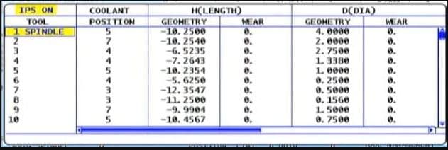
This is how they look on a Haas Machine
This tool length offsets file stays in the machine and is independent of your CNC Programs. So now any program can access this file.
So how does it do that?
It uses G43 and G43 says “ok get me a tool length offset”
G0 G43 Z3. H1
Which tool offset?? Well that’s the H number.
So the line above says to the machine rapid to Z3. Oh and by the way allow for the length of Tool 1 before you get there.
That’s the H1
So it gets the tool length from the tool length offsets file. It then does all the maths for you.
Actually it’s just a bit of simple arithmetic. Your (G54) work offset) minus your tool length.
Your tool will arrive 3mm above your component.
So whatever tool you called into the spindle with your M6 command you need to use the corresponding H number.
M6 T5 (Get tool 5 in the spindle) G90 G0 G54 X0 Y0 S1500 M3 (Rapid to X0 Y0 and start the spindle) G43 Z3. H5 (Rapid to Z3. but allow for the length of tool 5)
How do you measure the tools?
Well some people use a bit of paper!!!
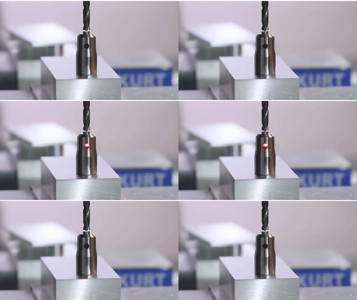
And some buy one of these little babies.
“It’s just a light on a fuckin stick” I hear you say. But it’s so much more. I comes on at an exact distance above your part. And because it’s all spring loaded, if the tool carries on a bit it don’t bust anything.
Only cheap but do a great job.
And if your a very good boy you might get one of these for Christmas.
Auto tool measurement (yes it’s all done for you)
In the cases above we are storing the actual tool length in the offset file.
Now let’s take a look at that tool file again.
Some of my readers are very astute but before you start writing me an email or commenting on this article. “oh David it looks like you fucked up again”
I know……
Why are the tool lengths (Under Geometry) minus figures?
That’s because as always there are several ways to do this. What some people do (and I am not one of them) is……
They bring each tool down from zero return and touch on the part. This figure is then recorded in the tool length offsets file. And yes it’s a minus figure. Of course the G54 work offset would be zero in the case of Z.
Now I am not prepared to argue with you about this (your doctor told me not to). It’s just bad.
That figure has no relation to the actual tool length and you need to reset every tool for every Job!!
I’m saying no more I’ll just wait for the comments.
There is Only One Way
Actually there is something else to consider. (I know I
said I’m saying no more).
By setting your tool length the correct way (my way), the stored offset is the actual tool length and you can do a rough check with your steel ruler before proving your program.
Auto tool length measurement will always give actual tool length and so will a tool pre-setter. That means you can swap tools between machines.
Well it’s easy. Mazak machines have active offsets so the minute you do a tool change and get your tool in the spindle the tool lengths offsets are active. They also nearly always have an auto tool measurement system
.
Sorry if you are a Mazak user and you are thinking “this dozy bastard has made me read all this gratuitous shit for nothing”
Now’s the time to leave. Go on off you go.
Ok so what.
Mazaks also do this…….
When you write a G code type program for a Mazak you don’t need a G43 and you don’t need the H
M6 T5 (Get tool 5 in the spindle) G90 G0 G54 X0 Y0 S1500 M3 (Rapid to X0 Y0 and start the spindle) Z3. (Rapid to Z3. but allow for the length of tool 5)
Forget the G43 H5 shit…. soooo easy.
Those Mazak guys just don’t believe in stating the obvious and wasting your precious finger tips typing in a load of bollocks that the machine should know anyway.
Just remember you can change this by parameter if you want it to work the same way as your Fanuc or your Haas. Oh and you don’t care about increasing your carbon footprint with those extra finger presses.
That way you can put programs from your Fanuc into your Mazak and vice versa.