Category Archives: Fanuc Mill

CNC Milling M Codes List For Beginners

CNC Training Call David: 07834 858 407

30 Five Star Reviews

CNC Training Centre Reviews

Contact CNC Training Centre


CNC Milling M Codes
List of M Codes for a CNC Milling Machine

Download CNC Milling M Code List

This is my list of CNC Milling M Codes and you will notice there aren’t many.

That’s because you don’t actually need many.

M Codes are used to turn things on and off on a CNC Milling Machine. Sometimes known as miscellaneous functions.

A typical M Code would be M03 which would start your spindle forwards.

M04 would be reverse and guess what?

M05 is stop the spindle.

There, you learned three already.

You don’t need the extra zero so I advise you leave it out, program M3 M4 M5.

It really doesn’t matter but….. You could be wasting memory space or wearing out the tips of your fingers.

Here’s what I think about leading zeros.

M codes are the Snow Leopards of CNC Machining

Snow Leopards are Solitary Animals

Snow Leopards only ever get together to mate, they don’t even have a Christmas party or get pissed on a stag night.

With M codes they hate being on the same line of code. If they are then they will fight to the death.

Tigers Playing

Please note no animals were hurt in the making of this post.

There are exceptions to this rule, M Codes that is, but please don’t overload yourself with this at the moment.

Just trust me.

The first one in the block usually wins but I can’t  guarantee it. So you could get some crazy shit happening.

G90 M8 G0 G54 X0 Y0 S1500 M3;

You wouldn’t even get an alarm on most controls and it may just obey the first M Code it sees and ignore the last one.

The other thing to note with M Codes is that it makes no difference where they are in a block of code.

So if you put your M Code at the front of a block of code.

M3 S1500 G0 X0 Y0;

Or the end.

G0 X0 Y0 S1500 M3 ;

The spindle will start according to the logic of the machine not where the M Code is in the block of code.

The Boring CNC Milling M Codes

That’s my list of M Codes the rest are really boring doing stuff like changing gear ranges and stuff.

Download CNC Milling M Code List

Sorry I’m being flippant again.

CNC Milling M Codes Where Are The Rest?

Sorry you can’t have them. The reason for this is that they are different depending on what machine they are on.

CNC Milling M Codes
Hand Em Over

For example this beast is a Mazak Megaturn

CNC Milling M Codes
Mazak Megaturn

It Has a Gearbox.

To change gear you program M41 M42 and M43 for the different gears

M40 is neutral. Now on machines with gearboxes they do normally use these same M Codes.

However they can be different.

M10….. mmmm well that’s normally a clamp.

I think you get the picture. It is up to the machine tool builder.

It is best to get a specific set of M Codes from your machine manual.

The manual by the way is that book that nobody ever reads, it’s usually at the bottom of a bent up old filing cabinet.

Please Don’t Read It

I’ll read it for you then charge you a shit load of money for training.

Click here for CNC Training

Joking aside please don’t be arsed to learn a load of M Codes you will probably never use.

Well Commented Programs

Try to put M Code descriptions in your program. That way you won’t need to keep looking them up. A part transfer on a CNC Lathe is a good example, there are an absolute shit load of em.

They are everywhere. If you put a meaning to each one in brackets it will make proving the program out really easy. Oh and if you have a CAM system then change your post processor to output them for you.

M11 (OPEN CHUCK)

M10 (OPEN CHUCK)

etc etc

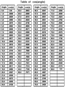
I had a boss once who actually learnt sines and cosines of angles.

Cosines of Angles

Holy shit I mean it’s impressive and I must add in 1975 it was actually worth doing because we didn’t even have calculators.

Hope you enjoyed reading my article on CNC Milling M Codes.

Please remember that it keeps me occupied and while I’m writing these articles I am not holding you up in the supermarkets queue trying to find a coupon for 10p off my incontinence briefs.

Download CNC Milling M Code List


Fanuc Display – Relative Position


CNC Training Call David: 07834 858 407

30 Five Star Reviews

CNC Training Centre Reviews

Contact CNC Training Centre


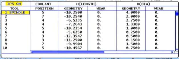
Fanuc Display (Relative Position) is used only by the operator.

Fanuc Display

You can reset Fanuc Display (Relative Position) just like you would on a manual machine with a DRO. So use it for setting or even measurements. One thing to remember is it will not retain it’s position when you turn the machine off. The control in the video is a Fanuc 18i on a big vertical lathe but all other Fanuc controls are similar.

Subscribe to my YouTube channel (I beg you)

“Read More”


Cutter Compensation

CNC Training Call David: 07834 858 407

30 Five Star Reviews

CNC Training Centre Reviews

Contact CNC Training Centre

Cutter compensation explained.

This is a video explaining cutter compensation in CNC programming.

You will come across various terms to describe this such as:

  •  Tool cutter comp.
  •  CNC cutter comp.
  •  G41 G42 cutter compensation.
  •  Cutter diameter compensation.
  •  Cutter radius compensation.
  •  Heidenhain RL RR.

Cutter compensation is referred to as cutter diameter compensation and cutter radius compensation

Haas cutter compensation, Fanuc cutter compensation and Mazak cutter compensation all work in the same way.

Although Heidenhain cutter compensation or Heidenhain cutter comp looks different. In the programme it functions in exactly the same way.

Cutter Compensation

In the parameters or settings of your control you can set up your system to use the radius or the diameter of your cutting tool.

This means that when you input the data for your cutting tool in your offset table you can use the diameter or the radius of the tool.  This depends on your settings.

Cutter Compensation

When people talk about cutter compensation G code they may say “cutter comp G code” it’s often shortened.
(Cutter compensation G code)
The G codes used in this video are:

  •  G41 cutter compensation left
  •  G42 cutter compensation right
  •  G40 G code to cancel cutter compensation

This Video shows you :

  • How to program G41.
  • How to program G42.
  • CNC cutter compensation examples.
  • Cutter compensation Heidenhain style.
  • Heidenhain RL RR.

We always recommend that you climb mill so you will be using G41 most of the time.

Milling the outside of a square using G41.

Cutter Compensation

Milling the inside of a square using G41.

Cutter Compensation

Milling the inside of a square using G42 (should you want to conventional mill).

Cutter Compensation

Milling the outside of a square using G42 (should you want to conventional mill)

Cutter Compensation


The rules when using compensation on a CNC Milling machine.

Rules are the same as the tool nose radius compensation on a CNC Lathe.
If you programme a shape and you do not use cutter compensation you will have to work out the size of the shape with your tool radius added.

This is simple on a square sided figure or a simple radius. Anything more complex and it’s a nightmare.
I just heard some smart arse say “Ah well my CAD system takes care of that”.
So it should my friend but, and there is a but:

  • What will you do when your cutter wears?
  • What if you want to use a different size cutter?
  • The cutter may not run true.
  • What if the cutter is not exactly size?

In the old days of paper tape and Corned Beef we as programmers would write several programmes.

This was so that we could re-grind the milling cutters in fixed increments. A different programme could be used each time the tool was changed.

Sorry I can’t talk about this much longer as I still have the nightmares (mainly about corned beef sandwiches).

Cutter Compensation


Anyway enough of that. So when we machine our first profile we can add some on to the tool radius in the offset file. When we check the part we can adjust the offset and re-cut the profile to achieve an accurate result.

The Rules:

  • Shape must be continuous and consistent.
  • You can’t cut along a line and then go back along it.
  • It’s important to allow more than the tool radius when entering tool compensation. The same applies when you come out of tool compensation.
  • Internal corner radii and steps must be greater than the tool radius.

Always allow more than the radius because when you adjust it it may be larger than the actual tool you are using.

Don’t ask

For example if you have a 12mm endmill but you have .2mm in the wear compensation. The machine thinks that the tool is 12.4mm in diameter.

You can’t do this in cutter comp:

Cutter Compensation

You would have to apply one cut in G41 and cancel with G40 then do another cut in G42 and cancel with G40:

Cutter Compensation

Call 07834 858 407

Please contact me if you require:

  • Fanuc training.
  • CNC programming training.
  • Want to Learn CNC programming.
  • Fanuc programming   training.
  • Yasnac programming training.
  • Any type of CNC course.

Don’t forget to watch my Tutorial Videos

Services offered at CNC Training Centre

Edgecam training.

Classroom programmer training.

Onsite CNC Machine Training.

CNC Training on all controls and machines.

Mazak Training Fanuc Training

Don’t forget we offer training on all types of Mazak Machines and all Fanuc Controls 6m to 31i Oi old to young.


Polar Programming G16 Fanuc

CNC Training Call David: 07834 858 407


CNC Training Centre Reviews

30 five star ratings on Google (Just saying)

Polar Programming G16

Polar programming is cool.

No one loves polar bears more than me.

Polar means you are working around a pole. So your programmed position is determined by a radius and an angle.

No use??? Think about it. Polar Programming G16.

Holes on a pitch circle. Mill a hexagon. Piece of piss. Honestly.

Read on….

Polar bears, polar programming here we go. Don’t go too close to polar bears as they have a propensity to rip you head off.

Oh No Polar Programming G16 is an Option

Sorry yes it’s n option. Anyway hopefully you have it. Don’t blame me blame the tight arse who bought the machine.

Imagine you had some holes like this to machine.

Polar Programming G16First thing you need to do is program a G16 to say you want to use polar programming.

G16 on its own means your datum is the centre of the pole (X0 Y0)

G16 X50. Y50. would put your pole centre at X50. Y50.

Anyway we want it at zero which is the centre of this pattern of holes. So it’s just G16.

Once G16 is active then X becomes your radius and Y becomes your angle.

What’s The Time Mr Wolf?

The angle is always measured from 3.15 as below. (If you’re reading this mum sorry about busting your clock but I needed the picture)

And the angle is measured counterclockwise. This applies to all CAD CAM.

So this angle would be Y60. (60 degrees) and the X would be X25. (Radius)

Polar Programming G16

So you program looks like this

Polar Programming G16

Now see it running.

Lets look at the milling in more detail

Polar Programming G16

Note that the distance to the sharp corner is 46.188 The line N1 uses this.

Polar Programming G16

Polar Programming G16 It’s So Easy

Then we just program each position as an angle (no need for the radius because it does not change)

Polar Programming G16

Each point you are going to has a radius from centre and an angle.

Incremental What’s That All About?

Don’t forget this works in incremental as well so be careful (you’re not insured for this)

Incremental

It gets even better when you use the L command.

Polar Programming G16

Polar Programming G16 Action

Now when it comes to the milling it’s so simple don’t you just love this.

Polar Programming G16

Action


What do you think?

G16…..

Add it to your digital toolbox??

Thanks

If you have been affected by any of the issues in this post or need CNC Counselling then contact me.

If you want to learn to program CNC Milling Machines

Look no further Contact CNC Training Centre


Ten Things You Might Not Know About The Fanuc Sub Program

CNC Training Call David: 07834 858 407


CNC Training Centre Reviews

30 five star ratings on Google (Just saying)

Sub Program Fanuc

Here are ten things you might not know about Fanuc sub programs,

Fanuc CNC controls are the most common controls in the world so it might be useful to have a good understanding of how sub programs are called and used.

(1) You Can Call a Sub Program By Name.

Yes you heard it here the program can be called by it’s name or it’s number. When calling by name don’t use the P.

Just put the name of the program in these things <> with an M98 and your away.

M98<ALBERT>

The only problem with this is that the syntax needs to be spot on so if you have got complicated names for your your sub routines then you might be in the shit.

I always call mine names like ALBERT that are easy to remember.

(2) You can use internal sub routines on a Fanuc Control.

Some people call these local sub programs. It just means it’s tagged on the end of your program which makes them nice n easy to look after. A bit like a pet Goldfish or a pet fly.

I bought mine from the local pet store. I asked the assistant if he sold pet flies and he said no. I said “well there are loads in the window”.

Anyway he sold me one (£15) his name is Paul


This is not him this is Steve.

Internal Sub-Routines

By typing M98 Q500 your control will look for N500 within your current program. This is great because you can add the sub programs to the end of your main program. Don’t forget to leave big gaps so you can clearly see where and what they are. Oh and mind your P’s and Q’s.

M98 P500 (Call O500 externally)

M98Q500 (Call N500 in main program.

Oh and read this too.

Sub Program

Just one other thing. Watch your n numbers it’s easy to get them mixed up. Try and use a convention.

“Read More”

Careers in CNC

View all current vacancies in CNC

Click here

Call David: 07834 858 407