Fanuc OT More Fun Than You Think
Category : Useful Stuff
CNC Lathe with very old Fanuc OT control.
I sometimes think I have the best job in the world apart from a few people like rock stars, pornstars and people who work in chocolate, and beer making facilities.

Everyday I get to work with interesting friendly people (apart from that bloke who knocked me out for accidentally deleting all his programmes). There are some very unreasonable people around. It took him less than three weeks to re-programme all the parts.
This week I worked at a company that makes lights n light fittings for posh restaurants and hotels.
Now I have never been allowed in a posh hotel or restaurant so I was amazed at all these fancy lights. The quality of the products these guys produce is absolutely stunning.
I got to train them on one of these.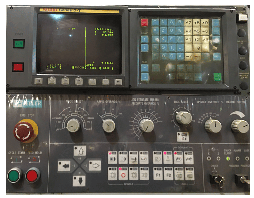
Now I know what you are thinking “Lucky Dave, that’s a beauty” but I can see straight through your sarcasm and please don’t keep calling me fuckin Dave, it’s David.
Anybody who reads my articles, and there’s only three of you,will know that I absolutely shit-faced love these old machines.
This one looks a bit shabby I admit but it’s previous user was not so gentle with it. A good service and some re-alignment and it’s back to to the workhorse it was meant to be.
Not to mension excellent training from me.

It’s old, but then so am I so lets not be ageist.
Got to be honest here. I had forgotten some of the little quirks to the old Fanuc OT control.
Dig Deep
Once you get your head around it there really ain’t much it wont do. There are variations on this control and this one didn’t have all the bells and whistles. You know like rigid tapping and macro.
I mean who needs all that complicated shit. I’d much rather keep breaking taps and not be able to parametrically control a CNC programme with the flexibility to make varying sized parts. Not to mention probing and automatic tool measurement. No no no bollocks to that keep it simple.
Joking aside dig deep and make sure you’re using everything it’s got.
I’m a great believer in working with what you have n with a body like mine believe you me you have to.

Anyway let’s get on with it.
MDI On The Fanuc OT
The MDI screen is not like the newer controls where you just write into programme O0000.
You type in commands and it fills in details on the screen.
You have to input each word of code separately, then when they are all on the screen hit cycle start or this green button.
Sorry but you are going to have to get used to all the shit pictures because it’s all I have access too.
If you don’t like it there are way more interesting sites than mine. Not about CNC by the way but there are so many good porn sites out there these days.
I mean it bores the arse off me, and I’m the one writing this crap!!
Haas Tip of The Day on Youtube is amazing try that.
Word of Warning in MDI
If you input a position move and a tool change in MDI. It will make the move first then do the tool change.
Wouldn’t recommend it.
This MDI is not like the newer ones where it’s a programme it’s just one page that gets filled in.
It’s OK once you get used to it.
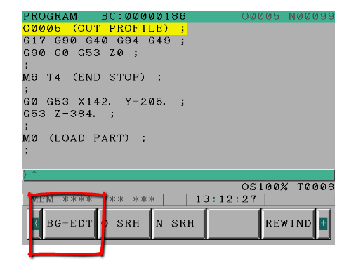
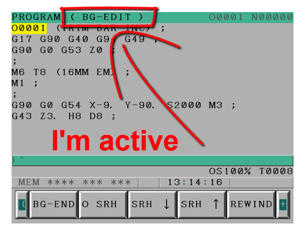
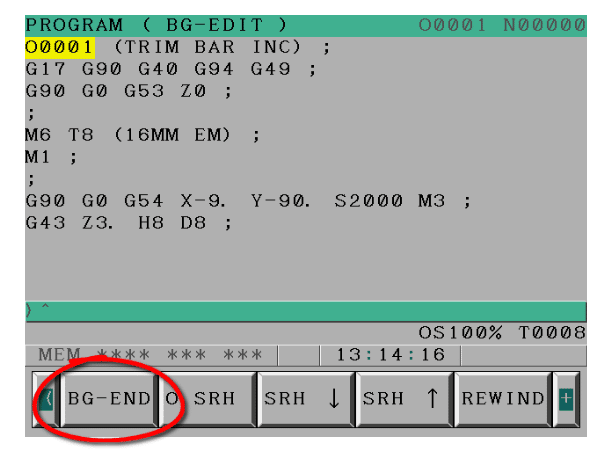
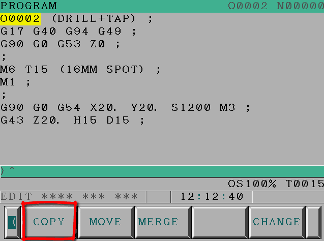
Programme Copy Fanuc OT
Editing is a little bit shit but once you get used to the protocol it’s not too bad. Try to change the way you look at this. I mean use the lower cursor arrow to search.

This is because the keys are quite cumbersome so if you can get into the habit of keying in the address, for example G or M, you can find the next G or M.
Or choose something more specific like G71 and then press your lower arrow to search.
I always feel sorry for these guys working in the chip shop where they have this thick polythene membrane over the keypad for the till. It’s pretty random which button they hit.
I paid £40 for fish and chips the other day (mind you the way inflation is going it was probably correct).

I said to the young lad serving me “is this fish cooked” he said “I’m sure it is”. I said “well it’s eaten half my fuckin chips”
Anyway this Fanuc keyboard was a bit like his. Maybe I should work in a chip shop, wonder if you get free chips?
Enough About Chip Shops
If you make yourself use the search key it will make the whole experience a lot less frustrating.
To copy programmes is long winded but worth the effort, press the extra edit key and then move to start of the bit you want. You then press the first cursor button. Move to the end of the bit you want to copy and press the other cursor button.
Programme Zero O0000
You then get to execute this. It’s all then placed into programme O0000.
Go back to your original programme and use the merge key to either merge this programme where the cursor is or add it to the end.
You can also change the programme number O0000 to another number, making a new programme.
When you are copying programmes you can use the ALL key for copying all of the programme.
When you use move or copy you can input a programme number so it does not go to programme O0000
This is not meant to be a full explanation but just to give you some idea of what can be done and get you excited.
So what the fuck is programme zero? Programme O000 is the programme number that the Fanuc control uses as a sort of clip board. When you use the merge button this programme O0000 is what it merges.
It even has find and replace.
End Of Block
My control had asterisks instead of semi colons for EOB (end of block)
This would annoy the shit out of me but it’s not my machine and I really couldn’t justify altering it and putting the users future in jeopardy.
If you don’t like this then just change parameter 10 bit 1


It really makes no difference it just looks different.
OCD
I often get accused of having OCD. People go around saying “oh it’s OCD”. When you just keep your work area tidy.
No fuck off, I like things tidy I’m a fuckin engineer.
If this is you then stop saying it. If you ever meet someone with real OCD you will be shocked. It’s a terrible condition it’s not just about keeping the knives straight in the bloody cutlery draw.
Rolls Royce 1971
When I worked at Rolls Royce in 1971 the guy who trained me was Ex-RAF and an absolutely amazing guy.
Reg his name was.
Reg knew I had a reputation as an apprentice for having absolutely no interest in work and just dreamt of being a rock star all day. Bit of a prick in those days but Reg didn’t seem to mind that.
This Really Is Me

Reg was a clever guy gave me a full sex education and taught me more about good engineering practises, in the six months I was in his care, than I have in my whole career.
He had a more subtle approach to training me. To start with he just used to talk to me and what stories he would tell. This guy was a fighter pilot in the second world war. The stories were amazing and mostly could not be used on this page. Even with my very low editorial standards.
He was talking one day about how much the guys used to swear and how ridiculous it got.
He was home on leave one day and the whole family had lunch together. Grand parents, aunties and uncles about 15 people for dinner.
All was silent as they all started to eat lunch, after they said prayers as they did in those days.
“Pass the fuckin salt” Reg said in a load voice completely forgetting where he was.
I found this story so fumy. There was an embarrassed silence and then everyone chatted on as if they hadn’t heard.
This guy believe it or not had a pet shop in the precinct in Coventry which he ran in his spare time.
He had a pet monkey. He told me how the monkey would sit on his shoulder whilst he served customers. The monkey found it amusing to stick his prick in Reg’s ear when he was serving customers.

I was so charmed and in ore of this guy that before I knew it I was assisting him to build gearboxes for the Nimbus Engine
He taught me basic skills like wire locking and how to correctly use spanners.
Before long I was assembling gear trains. I was really into motorbikes so a lot of the skill was transferable to what I was doing at home.

Fortunately i didn’t have one of these (Norton Jubilee) My mate did and it was an unreliable piece of crap.
The most important thing he taught me was the importance of keeping your work area spotless clean and all your tools neatly in place.
He knew where every spanner rachet and Allen key was and could drop his hand straight on any one without even looking.
If one tool was missing or out of place he would notice immediately. Imagine if you left a spanner inside an engine!

Oh and my workshop is still immaculate as you can see.
Being tidy is pragmatism not obbsessive compulsive dissorder.
OCD I rest my case.
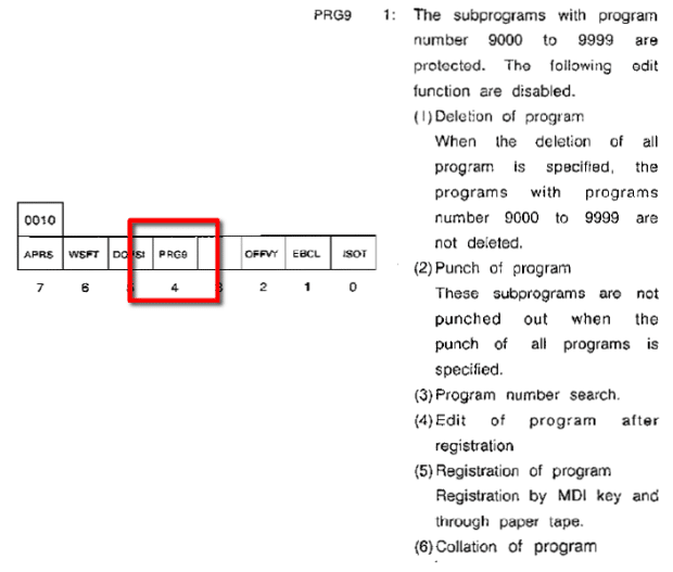
Other Exciting Parameters Fanuc Ot
You might want to fuck with some of the other parameters like these:

Parameter 40 bit 0 displays programme description in Library

Parameter 4 is to protect O9000 series programmes
Chamfer and Radii Fanuc OT
This control has the ability to add a radius or chamfer to a programme.
Just programme point to point and then add C or R as an after thought.
You learn something new every day.
My daughter is autistic so everything is taken in a very literal sense. I witnessed a friend drop straight into this trap. He was explaining how good it was to use a roller to paint furniture. yes, he said, “you learn something new everyday”.
Oh dear methinks.
I knew what was about to happen. “Mmm” my daughter said “what about yesterday?”
He thought she was joking, but no, she wanted to know exactly what he had learnt every day of that week.
When he said “It’s one of those things that people say”. I knew he was digging himself deeper and deeper into the shit.
I decided to pull him out. “It’s just a stupid neurotypical saying. It’s just not true”.
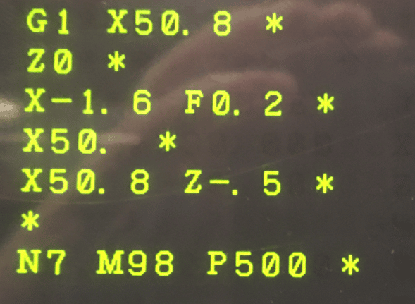
What I Learnt Today Fanuc OT
On this machine you don’t need a comma when you use R and C.
G1 X50. R10.
Z-20.
When I saw it I thought “mm where the fuck is the comma?”
Turns out there is a parameter to change it. (That’s what I learnt)

Don’t get this confused with G2 and G3. All you need with this is to programme the shape without the corner radius or chamfer (point to point) then just stuff in the pesky little C or R afterwards.
Authors Note:
I also learnt that there is no such word as learned. It’s learnt. Should have listened at school. (Smart arses please feel free to give me an English lesson.)
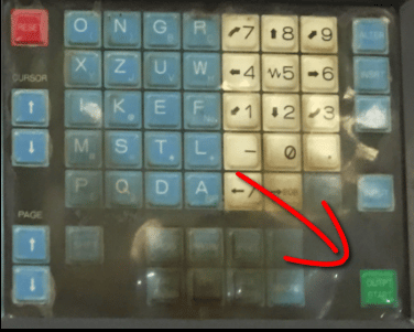
A Hidden Button Fanuc OT
Bet you didn’t know about this button.
Now I can tell you for sure there is nothing good about getting old. No no, it’s definitely the shit end of the chronological stick. It’s fucked up and I don’t like it.
You definitely get more patient with age. Like standing in queues. When I was young after five minutes in a queue I would rather remove my own appendix without anaesthetic than to stay another second.
Nowadays I just change into my slippers (which I have with me at all time in a carrier bag for life) and light up my pipe. Happily waiting for hours to be told “oh you can only do that online love”
People even call you “love” when you are old.

Have you ever noticed the No at the bottom of the F key? Anyway, I know the suspense is killing you. Well…. if you are on the offset page or the parameter page, when you press this key you will see No flashing on your screen. You can now input offset or parameter number and it will search for that number when you press input.
Now I know you’re thinking “this twat should find something better to do with his time” and you’re probably right.
The thing is if you force yourself to use all these little shortcuts then overall it will make a real improvement in efficiency. Oh and I’ve been watching you, you really need to up your game. Pissing around with that iphone all day.
It Will Make You More Efficient
Not to mention repetitive strain injury.
I often say to people who I’m training “I just read the manuals that you just can’t be arsed to read” and then charge you for training. They just laugh, mmm.
One More Really Important Thing
Now I know I’m banging on a bit about chip shops today but what the fuck is this thing about having gravy on chips!!!

Fuckin disgusting. Now I know it’s a northern thing and I know you northerners have some strange traditions but frankly this should be outlawed by public health.