Decimal Point Fanuc Parameter 3401
Category : Fanuc Parameters
Messing With Parameters Can Be Fatal!!!!!
Decimal Point Fanuc Parameter, to change this parameters you need to go to the setting screen in MDI. Now put a 1 in the parameter write box.
Today we are going to change the parameter that allows us to program with or without a decimal point.
Decimal Point Fanuc Parameter
If you set parameter 3401 BIT 0 (DPI) to a 1 then you can input numbers like a calculator.
X5000 will be taken as 5000mm
If you set parameter 3401 BIT 0 (DPI) to a 0 then your numbers will be taken as microns..
X5000 will be taken as X5 (in other words 5000 microns you would need to program X5000. to get 5000mm
X5000000 would also work

This should make it work. If it doesn’t then maybe you should call the Samaritans.
Decimal Point Fanuc Parameter Why?
It doesn’t really matter how you set this it’s entirely up to you. What I would recommend is that you make all your CNC machines behave in the same way.
Teach everyone to always input a decimal point and then if it’s needed then you got it.
Parameters You may Want to Change
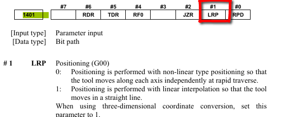
1401 Cutting Feed-Rate 0% stops movement of machine
3204 Unlock Program 9000 to 9999 and 8000 to 8999 to Edit
3291 Wear Offset requires Key to Adjust
3401 Calculator Type Decimal Point or Integer
3402 G Codes that are Active When The machine is Turned On
5003 Retain Geometry when you Press Reset
6005 Allows the Use of Local Subroutines (Newer Control)
6050-6059 Allows you to Call a 9000 series Program with a G Code
6080-6089 Allows you to Call a 9000 series Program with An M Code
8134 3453 allows you to use ,R and ,C (Rads and Chamfers)
That’s it away you go.
This guy has more CNC Manuals than you can shake a stick at.
Oh just one other thing before you go off and cripple your machine forever.

Do yourself a favor take a picture of the screen before you change a parameter. If you aint got a camera then you must have a piece of paper.
Even better back everything up.
Thanks
If you have been affected by any of the issues in this post or need CNC Counselling then contact me.
If you want to learn to program CNC Milling Machines
Look no further Contact CNC Training Centre