Author Archives: David

CNC Work Offsets G54 to G59 How to Use Them

As part of the basics of CNC Programming you need to have a good grasp of Work Offsets. This article explains how they work on various controls.

More Heidenhain

Make sure you read to the end to see how good use of Work Offsets can dramatically increase production on your CNC Machine.

So you wrote your program and it looks great on your simulation. Great but your machine hasn’t got a clue where your part is.

That’s where the work offset come in.

The control say’s “where the fuck’s the part?” machine says “ask the work offset G54 to G59 they’ll know”.

Drawing Datum

When we write a CNC program we work from a datum on the drawing. All the X and Y figures will be measured from this datum.

CNC Work Offsets G54 to G59

Once we put the component on the machine it needs to know where the part is.

This is called the work offset.

On  a Fanuc control it’s a G code usually G54 although as standard you have six of these.

G54 G55 G56 G57 G58 G59

Once you set one of these all you need do is use the G code (54 to 59) and the machine will use that offset.

Each one of these G Codes represents a datum position on the machine.

G0 G54 X0 Y0 (Rapid to X0 Y0 using G54)

G0 G55 X0 Y0 (Rapid to X0 Y0 using G55)

Because the work offset is modal once you state it you don’t need to repeat yourself. (It stays in)

Read this if you don’t know what modal means.

G0 G54 X0 Y0 (Rapid to X0 Y0 using G54)
X50. Y50. (Still rapid still G54)
Z10. (Don’t panic I know you still want rapid and G54)

Zero Return

When you first turn on your CNC Machine you would normally reference or Zero Return all the axis. The machine then knows where it is.

All machines will have a position display. This position display will have one set of figures normally called “MACHINE“. This is the machines position from zero return. So when the machine is at zero return this will read.

X 0.000
Y 0.000
Z 0.000

CNC Work Offsets G54 to G59

The “MACHINE” position tells us how far we are from the machine zero. We don’t use this once we have set our datums.

This is the position we need to write into the work offset page to tell the control where each datum is (G54 to G59)

What we do when we are setting (G54 to G59) is enter this position in the work offset page.

CNC Work Offsets G54 to G59

When we subsequently call this G code the machine will use this position as it’s datum.

On the screen above if you programmed G0 G54 X0 Y0 the machine would move -75. in X and –145.5 in Y. This is it’s new zero position. Every subsequent command will work from this datum.

Now Let’s Set The Work Offsets

What we do when we are setting the machines datums or Work Offsets is we tell the machine where our datum is from Zero Return.

CNC Work Offsets G54 to G59

In the above case the datum is 806.25 away from X Zero Return and 147.1 away from Y Zero Return. These will both be minus figures.

CNC Work Offsets G54 to G59

What about Z you say?

Well yes we need to do that also. The Z will be the distance from Zero return to the top of the work-piece.

CNC Work Offsets G54 to G59

So in the above case the distance from the spindle nose to the top of the work-piece is 530.570. Again this will be a minus figure.

CNC Work Offsets G54 to G59

So there you have it your work offset in X Y and Z.

This is how it looks in the offset file on a Haas machine.

This is an imperial (inch) machine so this datum is 12.568 inches away from the X zero and 8.489 from the Y zero.

CNC Work Offsets G54 to G59

On the Fanuc control below it has values set in G54 G55 and G56. you could use any of these offsets.

Not all machines will have minus figures in these offsets as the zero return can be in a different place.

Mazak Work Offsets

Now if this were on a Mazak control it would be exactly the same if you were using the machine in ISO G Code type programming.

CNC Training Mazak

If you were using Mazatrol and not ISO this would be recorded in a WPC. No that’s not a Woman Police Constable.

Anyway it looks the same it’s just that they call them WPC 1 and WPC 2 etc.

WPS’s are set in the program as you go along. It’s the sort of “pay as you go” datum system.

Toshiba BMC 800 Work Offsets

On the Toshiba BMC 800 machine which uses the Tosnuc Control, H numbers are used for Work Offsets H901 to H999. Even the greediest programmer won’t run out of work offsets on this machine.

Is Six Enough?

Unfortunately on most Fanuc Controls you only get six offsets G54 to G59 this should be enough really. Anyway you can get what is called “Extended Offsets” as an option this gives you another 99.

These are called G54.1 P1, G54.1 P2, G54 P3 etc etc. You get the idea?

They work in exactly the same way as G54 to G59 you just stick in a P number.

G0 G54 X0 Y0 (Work offset G54)

G0 G54.1 P1 X0 Y0 (Work offset G54.1 P1)

Right Let’s Wrap This Up

So what we did is told the machine where G54 was in it’s own master “Machine Coordinate System”.

So now if we program

G0 G54 X0 Y0 the machine will rapid to the position that we set as the datum. All subsequent moves will be around this G54 Datum.

Because G54 is Modal. 

Digital Readout

Imagine how difficult it would be if we had to keep adding all our figures onto the machine position. It’s just like when you have a manual machine with a Digital Readout (DRO).

You just clock up your datum position and Zero the display. Well that’s what this is doing on your CNC Machine.

The good news is you get to keep the position and there are six of them.

Toshiba BMC 800 Tosnuc 888 Control

Oh yea let’s come back to the Toshiba BMC 800 Tosnuc Control.

Toshiba Tosnuc CNC Training

This is one of my favourite controls. Call me a geek but I get really excited about this kind of stuff. Below is the 888 control. (The 666 is a bit of a devil to program)

Toshiba Tosnuc CNC Training

Considering how old these controls are they are packed with great functions. Sorry this is a blatant plug cos if you got one I’d love to train you on it.

On this control you would just record the figures in H901. The program would read.

G57 H901
G0 X0 Y0

The G57 activates H numbered offsets and it needs to be on a separate line.

So Where’s This All Going?

Now then think about this.

Once this offset is in the machine it stays in no matter what. Like the curry you spilt down your white shirt when you were pissed on Saturday. “It’s going nowhere”.

So where do the other offsets come in.

Well. Imagine you set this job up and the boss came over and said “Jack, can you fit in an urgent job before you do that one”

(Please substitute your own name above)

Don’t panic no need to punch the boss or tell him to stick his job up his arse. No no it’s easy. You smile and say “No problem sir I’ll leave that job set up in G54 and I will use G55 for your new job”

Don’t Just Plonk It Anywhere

Something I forgot to tell you. Always set your parts up as near to one end of the table as you possibly can. Never in the middle of the table. That way you get to leave the part on the table and set up another job.

So you would just load up another vice or whatever and set the datum in G55.

Now when you program.

G0 G55 X0 Y0

The machine will use the new datum…. Easy what.

By The Way

Oh and obviously if you call out your old program, for that job the boss doesn’t want yet, it will use G54. Everything will work around the old datum.

There’s More

A tool change on a modern machine is amazingly fast like a fraction of a second.

CNC Work Offsets G54 to G59

But we don’t all have super fast tool changers and I have worked on big machines where a tool change can be two minutes!!

Well let’s compromise. Your machine is a bit of n old banger.

Matsuura Training 500v

Actually these old Matsuura Machines with Yasnac Controls are awesome if you can get hold of one.

The tool change chip to chip is going to be about 17 seconds. Machines like the new Matsuura MX 520 tool change in just over a second. In my world that’s shit off a fuckin stick.

Lets Save Some Time

Imagine if we could get 17 parts on the machine table and set 17 datums. We pick up a spot drill. The tool change time is 17 seconds.

Ah but sunshine it’s gonna spot drill 17 parts so the tool change time really is only one second.

That’s 17 seconds divided by 17 parts. One second per part. It really is that simple.

It’s A Myth Size Really Does Matter

I had you fooled there just when you thought I was talking about Pizzas. I was talking about machines.

Mazak Training

Look at the size of this Mazak Machining Centre it has the new Mazak Smooth Technology control.

Imagine you have an old machine but it has a huge table. Well if you fill the table with parts suddenly your slow tool changer does not matter.

Oh and about the slow rapid moves.

Doesn’t matter either.

The longest rapid moves are the ones to and from tool change. But we took care of them because one tool change does 17 parts.

From part to part there are only small rapid moves so we gain there too.

So our big old Tortoise can beat the Young Fast Hare.

Now The Bit You All Waited For

Work Offset G54 G55 G56

CNC Work Offsets G54 to G59

CNC Work Offsets G54 to G59

So these figures above would be entered into your work Offsets.

This is how it looks when it machines all three parts. No wasted moves and your making maximum use of each tool.

Another thing, notice how the drill starts at one end and instead of going all the way back. The next tool starts where the last one finished.

This won’t be possible on some machines but on most you can tool change wherever you want.

Lets Take A Look Under The Bonnet


The program looks something like this.

Just by putting the new work offset in front of the X and Y figures will make the coordinate system swap to the new work offset.

And…

Because the G code is modal it stays active until you call a different work offset.

Heidenhain

Found on a lot of Bridgeport Machines like the Interact 412, the Heidenhain Control can use the same method as above. You would have an offset table the same where all your offsets are stored.

Bridgeport Interact 412

Great little machines Bridgeport Interact 412 still loads of these in service.

These are then called out by numbers.

Heidenhain Training

This would call out offset 1.

Heidenhain There’s Always a Simple Way

Just zero the display.

How easy is that?

Mmm don’t be confused. That really is all you do and your datum is set.

When you want a different datum you just use a datum shift command.

Heidenhain Training

This would shift the datum by the above amount from your zero. And to change it back.

Heidenhain Training

These can be put in Label commands so that they can be retrieved and used again.

Heidenhain Training

Oh and you can have as many of these as you like.

So there you go from Heidenhain on a Bridgeport Machine to Matsuura MX520 with a Matsuura G-Tech 31i control. There are loads of different machines but the principle is always the same.

Understand one and you’ll easily understand them all.

Thanks For Reading

Don’t forget there’s loads more folks.

And a YouTube channel

Call David 07834 858 407

Learn CNC Programming

Services offered at CNC Training Centre

Classroom programmer training.

Onsite CNC Machine Training.

CNC Programming and Training on all controls and machines.

Mazak Training Fanuc Training

Don’t forget we offer training on all types of Mazak Machines and all Fanuc Controls 6m to 31i Oi old to young.


G02 G03 Circular Interpolation

G02 G03 Circular Interpolation

On a Fanuc or Haas control G02 G03 are the two G codes we use to move around clockwise and counterclockwise circles. You don’t need the leading zeros so from now on I will call them G2 and G3.

And by the way never use the letter O it’s number zero

GO2 GO3 looks almost exactly the same as G02 G03. But your control will blow it’s mind and get real mad with you.

It will also do some really weird shit like trying to start a new program. Anyway just don’t do it.

If you want to know how to do this on your Heidenhain control you need to read this article.

Oh and please don’t call it interpolation as it annoys the shit out of me.

  • Linear interpolation is movement in a straight line.
  • Circular interpolation in moving in a circle.
  • Interpolation is movement.

Now that’s the telling off out of the way let’s move on. It’s ok I don’t hold a grudge.

Which one of you bastards said interpolation?

Let’ Talk About Milling A Shape

When you are milling a shape and you want to move in a circular motion you use G2 or G3

For a clockwise arc use G2 and for a counter clockwise arc use G3.

They both work the same way. On a modern control you programme the endpoint (an XY figure on a milling machine) and the radius you require.

Then your CNC controller magically creates your circle. You can programme any arc like this with one exception.

Do you know what it is?

Ok I will tell you later, it’s OK to not know. (Just means you are little thick).

Lets go back to school.

Remember construction? Of course you do.

We are going to mill the top section of this part

G02 G03

Let’s see what the control has to do to work out where the centre of the circle is.

It knows its current position and in your G3 line you tell it the end point and the radius you want.

G02 G03

Well it gets out its little compasses and draws two circles at the radius you told it.

G02 G03


It positions the compass first on the start point and draws an arc. Then on the end point and draws an arc.

Where these two arcs cross it places the point of the compass. Now it can strike an arc that touches your start point and your end point.

Get yourself a pair of compasses and try it. It’s great fun.


G02 G03


That’s how the maths works.

Tell me did you really believe that inside your CNC machine there is a little man with a pair of compasses?

Fuckin hell I give up.

Sorry I lied it’s all done with simple trigonometry. But at least I tricked you into understanding the principle.


g02 g03 lathe

So you should now begin to work out why you get an alarm when the radius is too small. Your two arcs just don’t cross. In other words you are trying to fit an arc between two point that simply miss one another.

G2 G3 No Pot of Gold

Your control will give you an alarm “End Point Not Found” which makes sense because it can’t find one. It’s like the pot of gold at the end of the rainbow.


G02 G03

Oh Before you Go More on G02 G03

What about the question. When can you not use endpoint and radius with G02 and G03 ?

Answer: When you want to machine a full circle using G02 and G03.

You can do it but you would have to break it into two halves. I’m not going to explain anymore because this method is for wimps and peole who can’t be arsed to read my articles.

You know who you are, ordering Chicken Korma in an Indian Restaurant.

Well…… what follows is a full, blow your bollocks off, shit your pants the next day, vindaloo.

And Now Ladies and Gentlemen the Infamous I and J

At the CNC Training Centre we don’t get too excited about I and J when it comes to programming circles. That’s because you don’t need to worry your pretty head about it anymore. You almost never need it.

Did he say almost?

Well yes almost. You could programme forever and never bother about using I and J with G02 G03. So just go off and watch some porn for awhile and I will explain to the real programmers when you can use it.

In the old days I and J was the only way to programme an arc. You would tell the control where the centre of the circle is and the endpoint. This is cumbersome and a bit tricky. That’s why I’m not telling you about it.

Anyway one really good simple way to use I and J is for a full circle. Oh and it’s bloody easy. That is once I’ve explained it to you.

Click here for more info on full circle

When I was a boy hundreds of years ago I had a toy called a Spiro Graph.

Spirograph those were the days

It consisted of a series of plastic gears. You stuck your pen in a hole in the gear and rotated it around another gear. With a bit of practice you could make some really nice pictures. Kept us happy for hours. The crime rate dropped dramatically in my area when these things came out.

What’s this to do with CNC programming you ask? Well if you tried to use end point and radius for a full circle this is what you would get:

If your start point was X0 Y0 you would program G3 X0 Y0 R100. assuming radius was 100mm.

So in a full circle your endpoint is the same as your start point. There are millions of circles the computer could pick. It would be just like the shapes above. If you do the compass trick you will see what I mean. That’s why it’s impossible.

In Comes I and J

G02 G03

So some clever bloke thought fucks this I’ll invent I and J.

If we use I and J there are four options as above.

You would simply program as below for a full circle (20mm Radius)

  • G3 I-20.
  • G3 I20.
  • G3 J20.
  • G3 J-20.

And that’s it.

G02 G03

So these are the four options


G02 G03

So there you have a fantastic way to programme a full circle without having to break it down into two halves or be clever like a newsreader or some twat off mastermind.

Why do you only need the I and not X and Y Dave?

For fucks sake don’t call me Dave my name is David.

I had this really nice guy phone me from Africa the other day. He explained to me that he needed to get his inheritance of 10 million pounds out of England and if I helped him he would give me £20,000. All I had to do was give him all my bank and credit card details. Oh and a small one off payment of £1000.

Of course I agreed, what a bargain. Just as I was about to do this the cheeky bastard called me Dave.

I immediately told him to fuck off. I just hate being called Dave.

I gave him my 96 year old mothers phone number because I thought at least she can benefit from it all. Her name is Mary so he couldn’t shorten that. She only has £1200 in savings so it would be doing her a massive favour.


Explanation

You don’t need to re-state the X  and Y because you are already at the endpoint

Click here for more info on full circle

If you want to do this on a Sinumeric Siemens 840D read this

Thanks For Reading

Don’t forget there’s loads more folks.

And a YouTube channel

Services offered at CNC Training Centre

Edgecam training.

Classroom programmer training.

Onsite CNC Machine Training.

CNC Training on all controls and machines.

Mazak Training Fanuc Training

Siemens Sinumerik

Don’t forget we offer training on all types of Mazak Machines and all Fanuc Controls 6m to 31i Oi old to young.


Absolute or Incremental G91 G90

Absolute or Incremental that is the question?

Absolute or Incremental no it’s not a Shakespearean Quote from Hamlet.

Two distinct ways of programming.

We all know Absolute (G90)

You are working from an absolute datum. This means that every position or movement is a measurement from the datum.

It is just like on a drawing where every measurement is from the same datum point.

Absolute or Incremental

So no matter what position you move to the movement distance is from the datum. This is called Absolute and you use G90. G90 is modal so the G code stays in until you tell the control otherwise.

Absolute or Incremental

But do you understand Incremental (G91)???

Incremental is a bit harder to get your head around.

Absolute or Incremental

So this time it’s like every position is measured from where you are. So if the movement is X10. then the machine moves 10mm from where you are in a plus direction.

Here is the same part as above but drawn in a different way.

Absolute or Incremental

So each position is measured from the last one. Well that’s how incremental positions work. You just move the incremental distance regardless of where you are.

Absolute or Incremental Why?

Come on you tell me…….

You’ll have to work it out or read right to the end of this article. Oh by the way it’s incredibly boring.

Absolute or Incremental There is More

Absolute is like saying “Go to my house”. My house is in just one place and I only have one. So that is an absolute position.

Now if you were at my house and I said “Go to my house”. Apart from thinking I am a bit daft you wouldn’t move. You’d say “David, I am already at your house, are you OK?”

Absolute or Incremental

Well that’s like being in G90 Absolute.
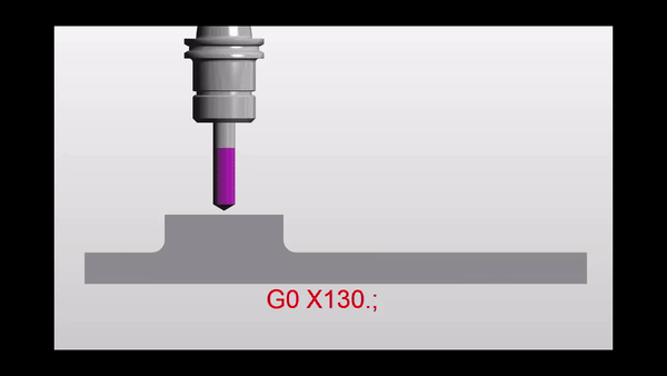
G90 G0 X50. Y50.
X50. Y50.

When the machine gets to the second line, in the above code, it wouldn’t move. It would quite happily accept this line of code. I’m sure somewhere deep in it’s CNC brain it would think you were a bit daft. But they are very polite these CNC guys.

If you were in a canned cycle it would drill another hole in the same place because that is what a canned cycle does. (They repeat each time a position is given)

Ok Now are you ready? The Incremental Bit

So if I said to you “drive 5 miles north”.

Well it rather depends on where you are. You may well arrive at my house (and I would make you a cup of tea). Now if I repeated the command “drive 5 miles north” you wouldn’t stay for another cup of tea. You have another journey to make.

Well that’s like being in G91 Incremental.

G91 G0 X50. Y50.
X50. Y50.

After the second move in the above code you would be at X100. Y100. Each axis moves another 50mm.

The Wait Is Over Read On

Absolute or Incremental, why?

First of all let’s look at the two drawings again.

Absolute or IncrementalAbsolute or Incremental

Why not just read the figures off the drawing? Dead easy. First drawing would suit absolute. Second drawing would suit incremental. Or for some parts it would be a combination of Absolute or Incremental.

If you try to add up the figures on drawing number two you will more than likely make a mistake.

Reading The Program

When you read a CNC program you want the figures you see to be the same as the drawing. That way it’s easy to check and you won’t make so many mistakes.

Don’t forget it might be years later when you next read this program.

Absolute or Incremental

So Absolute or Incremental? Well it rather depends.

Here is another example where incremental programming would work well.

Absolute or Incremental

The pockets are all the same so you could program one pocket incrementally. Stick it all in a sub program and then just move to an absolute position and call it out.

It would be a bit like having a robot that could dig ten inch diameter holes two foot deep. You just send it anywhere in your garden, it will dig you a hole and you can plant a tree.

Absolute or Incremental

I can almost hear the comments on this article. “Oh I’d just use a different datum for each pocket”.

“Incremental no way bloody dangerous”

OK smart arse.

At the CNC Training Centre we like you to learn as much as possible about CNC Programming. Understand all the G codes all the M codes every principle. You end up with a toolbox full of CNC Programming Tools.

Absolute or Incremental Which Tool?


Absolute or Incremental

So Let’s Talk About Safety

When you use G91 Incremental as soon as possible add a G90 to bring the machine back to G90 Absolute.

So for example if you had a sub-program you could try and remember to put G90 in your main program. That is something I would definitely forget to do.

So put it at the end of your sub program. That way every time you come out of your sub program you are back in G90 Absolute.

O500(Drilling Sub-Program)
G91(Incremental)
X50.
X60.
X80.
X10.
X5.
X5.
G90(Absolute)
M99

It’s all about tidying up.

Absolute or Incremental

If you leave things lying around anything can happen.

You definitely can have a collision using G91 (Incremental) if you are not careful.

Don’t Be Put Off There’s More

Incremental has some brilliant uses. When drilling holes the same distance apart it can save you a lot of programming time. Oh and it really simplifies things.

When using a canned cycle like G81 you can make repeat moves.

G81 G98 Z-5. R1. F100.
X52.554 L20
G80

This will drill 20 holes 52.554mm apart. Think about adding all these figures up, very prone to mistakes.

But do be careful, if you get a figure wrong you can get a cumulative error. “Cumulative error” Sorry I promised not to fuckin swear.

Come on you G91 deniers it does exist and it can work.

Advantages

  1. You can program exactly what is on the drawing.
  2. No need to add up figures.
  3. Repeat holes are dead easy.
  4. Features that repeat can be placed in a sub program and used at any absolute position.
  5. Less errors because you don’t need to add up the figures.
  6. When you later read your program the figures look like the ones on the drawing.
  7. Great for using sub-programs.
  8. It can help you lose weight as part of a calorie controlled diet.

Disadvantages

  1. If you make a mistake then the errors will add up.
  2. Can cause collisions if used incorrectly.
  3. People don’t like it and are frightened of it.

stamp-895385

Remember

  • Change back to Absolute G90 straight after use.
  • Make sure the figures you input are accurate.
  • Standardise your code (Read This).
  • After each tool change make sure you have a G90.
  • When you are proving out look at position display to check how figures add up.

Thanks For Reading

Don’t forget there’s loads more folks.

And a YouTube channel

Learn CNC Programming

Services offered at CNC Training Centre

Edgecam training.

Classroom programmer training.

Onsite CNC Machine Training.

CNC Training on all controls and machines.

Mazak Training Fanuc Training

Don’t forget we offer training on all types of Mazak Machines and all Fanuc Controls 6m to 31i Oi old to young.


Learn CNC Canned Cycles G81 G84 G73

Learn CNC Programming (Canned Cycles)

A Canned Cycle What is It?

If you want to learn CNC programming  then you need to know what a canned cycle is.

I’m going to have to be honest here it is a funny choice of words “Canned Cycle”. But a wild guess would be that all the information to drill a hole would be kept together in a “Can” ready to use.

In a Can…….Learn CNC

So let’s learn CNC Programming….

Make sure you read the end of this article to see a really cool way to drill equally spaced holes.

First of all we state the cycle:

G81 Z-20. R1. F100. X50. Y50. F200.

The machine will move to X50. Y50. then rapid to 1mm above the part (this is the R1.). It will then feed down to Z-20. at a feedrate of 200 mm per minute F200.

Finally it will rapid out of the hole.

It then sits ready for the next move.

dog-163527

All you need to do now is just keep giving positions.

G81 Z-20. R1. F100. X50. Y50. F200.
X60.
X70.
X80.
X90. Y60.
G80
The G80 at the end will cancel the canned cycle. It just means “Look I am a bit pissed off with drilling holes so can you stop”

So that’s it Canned Cycles it really is that easy you put all the information in the “Can” then each time you give a position you get another hole.

Want to know More?

Thought you would. You want to learn CNC programming don’t you?

There are loads of these canned cycle but I am not going to talk about every one in detail. No sorry you will have to read the boring old manual for that.

Not to Worry They Are All The Same

Well sort of. You state the cycle then it repeats at each position given until you cancel it (and that applies to all the cycles).

Anyway Here are a few:

G84 taps holes, tell it the pitch depth usual stuff.


G73 peck drilling is the same as drilling (G81) but you give it the peck depth.It pecks the hole breaking up the swarf.


G83 same as G73 but with each peck the drill comes right out of the hole. For deep holes or swarf that clogs.


G76 bores a hole, stops at the bottom, moves over and rapids out to avoid marking the bore.

Ok let me tell you this, you are doing great so far. This is how we learn CNC programming. Nice small steps.

G98 G99

I already wrote a post on this click to see it all (it’s truly amazing). I purposely didn’t include it in the cycle above which is ok. The idea was to keep it simple.

 G43 Z50.H1 M8

G81 G98 Z-20. R1. F100. X50. Y50. F200.
X60.
X70. G99
X80.
X85. G98
X90. Y60.
G80

g98gif

All it is in a nutshell. G98 returns to the Z point you were at before you started the canned cycle.

G99 will return to the R point (R1.)

Why you ask?

Easy you can jump over shit.

Clamps, high sections on a part, tall buildings, anything.

spiderman-1579249

It Gets Better.

G81 Z-20. R1. F100. X50. Y50. F200.

The Z-20. the R1. the feed-rate etc are all known as parameters. These are the things that control your cycle.

These can be altered at anytime and stay in until you alter them again or cancel the cycle.

G81 Z-20. R1. F100. X50. Y50. F200.
X60.
X70. Z-30. (From here onwards the holes are drilled 30mm deep not 20)
X80.
X90. Y60.
G80

Now let’s alter the feed

G81 Z-20. R1. F100. X50. Y50. F200.
X60. F300. (Change feed)
X70.
X80.F200.(Change it back)
X90. Y60.
G80

Remember it stays in until you say otherwise.

I Think you Now Need to Learn About Modal Information

Read the above article. Modal means that the information stays in the control until you cancel it or change it.

Do’s And Don’ts

Do Not………

Put in a rapid command G0 X50. Y50. it will cancel your cycle and the machine will just sit laughing at you. (No hole drilled).

See this post G0 cancels canned cycle.

G81 Z-20. R1. F100. X50. Y50. F200.
X60.
G0 X70. (Rapid to X70. no hole drilled)
X80. (Rapid to X80. no hole drilled)
X90. Y60. (ETC)
G80 (You already cancelled the cycle with G0)

Do Not Repeat Axis Moves. 

G81 Z-20. R1. F100. X50. Y50. F200.
X60. Y50. (Don’t need Y50.)
X70.
X80.
X90. Y60.
G80

D0…….

  • Always use a canned cycle if possible it saves loads of time. It is also really easy if you need to edit anything.
  • Make your CAD/CAM system output canned cycles, not long hand code. I saves loads of time if you need to edit.
  • Love engineering and be nice to your cat.

 Really cool way to drill equally spaced holes

Imagine you need to drill and tap this part. Nine M10 holes.


Learn CNC


Learn CNC


Quite simple but 31.63 added up nine times? Mmmm I never learned my 31.63 times table.

O0001(Drill and Tap M10)

T01 M06 (20mm Spot Drill)

G90 G0 G54 X0 Y0 S1500 M3

G43 Z3. H1 M8
G81 G98 Z-10. R1. F100 L0
G91 X-31.63 L9
G80
G0 G53 Z0
ETC
M30

Learn CNC Programming? How easy is that?

  • The programme moves to the datum X0 Y0 which is the middle of the part at the right hand end.
  • The G81 has an L0 at the end. L0 is not a Lionel Richie song it just means don’t do one. So it moves to X0 Y0 and does nothing.
  • The next line, G91 means incremental move so it moves incrementally nine times (L9) X-31.63 and drills a hole each time.

Brilliant I told you it was worth waiting for.


Learn CNC


Thanks For Reading

Don’t forget there’s loads more folks.

And a YouTube channel

Call David: 07834 858 407

Learn CNC Programming

Services offered at CNC Training Centre

Edgecam training.

Classroom programmer training.

Onsite CNC Machine Training.

CNC Training on all controls and machines.

Mazak Training Fanuc Training

Don’t forget we offer training on all types of Mazak Machines and all Fanuc Controls 6m to 31i Oi old to young.


Avoid CNC Crashes Don’t Reinvent the Wheel

Category : Useful Stuff

This is an article designed to help you avoid CNC crashes.

Avoid CNC Crashes

I listened to a fantastic documentary on Radio 4 the other day about Airline Crashes. The program explained how the hierarchy (cabin crew, flight crew) caused wrong decisions to be made.

In the Kegworth air Crash, cabin crew knew that the pilot had shut down the wrong engine. Unbelievably no one felt empowered to tell the pilot. The program went on to explain about “The No Blame Culture” and how they had taken this further and created a system where everyone could speak out.

Although this is not the main crux of my post it does highlight some of the points I want to make.

So when a machine crashes. What do you do?

  1. Whose fault is it?
  2. How easy will it be to fire this person?
  3. How quick can we get the machine running again and make some parts?


WRONG!!!!


Avoid CNC Crashes


The above are all the things I definitely would not do.

LinkedIn is full of all these soundbites and bulshit.

Quick one word banners. You know the stuff.

Avoid CNC Crashes“Don’t Eat Yellow Snow”. Well maybe that’s not one on LinkedIn but you know the sort of stuff I mean.


Anyway I bet there is one about making disasters into learning opportunities.

If you know one then send it to me. Cos I agree.

So when you have a collision on a CNC Machine here is what you do.


  1. Make it very easy for everyone to tell you exactly what has happened.

  2. Do not apportion blame. It must be seen as a way to improve things (a learning opportunity).

  3. Make a detailed report on the whole incident.

  4. Analyse the report with all parties involved.


When you analyze the information you have gathered, try to break it down into small parts.

(Oh and by the way if you think this is a waste of time work out what the collision just cost you.)

Each time you spot something wrong come up with a permanent solution so that it can never happen again.

The idea is that you only make the mistake once. If you say things like “he’s an idiot”. What are you going to do about that? Well maybe you could sack him. That is after he punched you for calling him a twat.

Sorry but this won’t work. Next time you inadvertently employ an idiot your machine will get broken again.

Avoid CNC Crashes

Now the idea is to Avoid CNC Crashes. If an idiot can operate the machine and not crash it then we have a solution.

I once suggested in a meeting that we fire all the machine operators. The management team had gone on at length about all the problems with staff and how useless they were.

man-110307

What would we do then? I was asked. Well we will recruit more. What would we get?

  • A moaner.
  • Someone who is  often late.
  • A person who has loads of sick days.
  • The guy who crashes machines.
  • A brilliant worker.
  • A total prick.
  • One not so brilliant worker.

Actually you would get what you have now. So the message is to work with the staff you have and get the best out of them.

So an example would be:

An operator altered a program and made a mistake. This resulted in the machine crashing.

We could carefully analyze what happened and come up with solutions. These would then become part of everyday procedures,

  1. You could remove the edit key so that operators needed supervision to alter programs.
  2. You could make a tutorial video on the prove-out procedure after program alteration. Then get all involved to view it.
  3.  What did he alter wrong? Maybe there is a training issue.
  4. Maybe he missed out a decimal point and needs to read my post.


Some ideas below on how to help Avoid CNC Crashes.


Wrong Offset

Always prove out correctly remember the movement after the tool change is very often the most dangerous one as this is when the offset is applied.

Always adjust the wear offset not the big number (Geometry)

You can also restrict the value it can be adjusted by read this.

What changed?

If program has been used many times before. There should be a procedure in place to keep it in a special folder marked “proven”.

  1. You may be using different tools so did you edit the tool numbers?
  2. Do  the offsets correspond to the tool numbers H and T? read this.

The Rules

If this is an existing program then the first tool moving toward the part is the most dangerous move.

  • Your work offset could be wrong.
  • Tool measurement could be wrong.

Once this first tool is proven correct then you know your work offset and your first tool are correct. Beware if the work offset changes say from G54 to G55.

G54 may be fine but what about G55?

From now on you need to check the line  where each tool comes into the component.

Once the tool is in use it’s happy days. Just keep an eye out for changes in work offset (G54 to G59).

Use your  check screen.

Avoid CNC Crashes

From this you can see all the information you need

Avoid CNC Crashes


Absolute Incremental (Don’t be afraid to use it)

If you use G91 (incremental) make sure you immediately program G90 (Absolute).

To move the tool to the tool change position it is much safer to use G53 Z0 rather than G28 G91 Z0. That way you don’t need to remember to change back to G90.

If you are using a sub-program end it with G90 and begin with G91 that way you won’t forget.

Switch To G90 ASAP

In the parameters of most machines you can set it so that when you press reset the machine will revert back to G90.

Read this on machine wake up state.


G91 is very safe to use if you follow the rules.


Decimal Points

Some controls will take calculator type inputs. X20 will be X 20.00. Beware this can be read as X.020 and there is a big difference.

Fanuc, Haas and Mazak will allow you to set a parameter that allows either.


Read this post first.

Speed Clamps On CNC Lathes (Avoid CNC Crashes)

G50 is really important it should be at the head of every program or possibly on every tool.

G50 S2000 (speed will not go over 2000 rpm)


Avoid CNC Crashes


Services offered at CNC Training Centre

Edgecam training.

Classroom programmer training.

Onsite CNC Machine Training.

CNC Training on all controls and machines.

Mazak Training Fanuc Training

Don’t forget we offer training on all types of Mazak Machines and all Fanuc Controls 6m to 31i Oi old to young.


WP to LinkedIn Auto Publish Powered By : XYZScripts.com