G28 is used to send a machine to Zero return for a tool change or at the end of a program. G28 G91 Z0 (Z axis moves up to tool-change)
G28 G91 X0 Y0 Z0 (All three axis move to their respective zero return positions)
I know some of you don’t like three axis moves like the one above. If it don’t hit anything it’s just fine “Get Over It”
Below are the two ways of doing this.
Ignore This If You Get Bored Easily
G28 actually means return to the zero point via a reference point.
If you programmed G28 G90 Z0 or you forgot the G91 this means return to zero point via a reference point. The reference point is Z0 so the spindle would rapid to Z0 (Bang) and then move up to reference return point.
That’s why if you have single block on you will notice this is two presses of the cycle start (two blocks).
Therefore if we use G28 G91 Z0 the first press will take it to the reference point which is incrementally zero form where you are (no move) the second press move to zero (no collision)
Using G53
Some older machines won’t have this so try not to get over excited.
G53 uses your absolute machine position (Machine) this means all moves are from home position and are not affected by datums (G54 etc) or tool length offsets.
It is one of the very few non modal commands so you can’t write
G53 Z0 X0 Y0 (this will use works offset not G53)
You need to write G53 Z0 G53 X0 Y0
Advantages Disadvantages (G28 G53 Zero Return)
G28 uses G91 incremental so you must remember to write G90 (absolute) for your next command. In fact many a collision is caused by misuse of G28.
G53 is best if you have it just remember it is non modal.
So you write it in each time you need it.
Note:
Some machines have return to tool change built into the tool change line. T01 M6
On a Haas machine for example where the return command is built in you would not need to send the Z axis home.
I recommend that you always put one in. G53 Z0 T01 M6
If you are in single block you can stop before the tool-change if you wish.
Also I know someone who got into the habit of doing this and crashed a Fanuc Controlled machine that needed the command. (If you read this you know who you are)
G53 has another really good use and that is if you want the machine table (on a vertical machining centre) to move to a standard position to do things like changing the parts. It will always put the table in the same place regardless of work offset.
Bare in mind that if you put a position in that is relative to your work offset and not use G53 then the next time you set the fixture up your machine may over-travel because the fixture is in a different place.
If you read this article you will see how it could be used to set a vice in a known position regardless of datum.
Remember G53 is a position from the machine zero, it does not take into account the tool length offset or the datum. The other important thing is that it is non modal. That means you will need it on every line that you wish to use it for.
On Machines Like The BMC 800 from Toshiba
This machine has the Tosnuc 888 control.
For this control use G73 instead of G53.
If you have any questions about G28 G53 Zero Return or you are affected or have been affected by any of the issues in this post please contact me 07834 858 407
G98 and G99, a canned cycle is usually one line of code for example to drill a hole. This one line of code tells the machine all it needs to know about drilling my holes.
Depth
Feed-rate
A point in the Z axis to rapid to before drilling
Point to rapid back to after drilling
G81 Drilling Cycle Sample Program G98 and G99
What happens then is each time you give the machine a new position it will drill one of these holes.
This is great because you don’t have to worry about what’s going to happen.
Each hole will be identical unless you change one of the parameters in the cycle like the Z depth or the feed-rate.
Therefore if on one hole you put a different Z depth that hole and all subsequent holes will be to the new depth.
Easy As ABC
So all in all it’s a really easy way to drill holes. You tell it what you want and then each time you give a position you get a hole. Then when you get sick of drilling holes you type in G80 and it stops drilling holes.
Machine says “OK this turkey doesn’t want anymore holes” so from now on when the machine moves to a position nothing happens.
Mitsubishi Drill In Action
Mitsubishi Carbide
There are loads of Canned Cycles I can’t be bothered to tell you about them all cos I’m going out tonight otherwise I would explain them all. If you scrat around this website for a while you’ll find them all.
They all work in the same way but with some variations.
Now the video at the bottom of the page is about G98 and G99.
G98 and G99 are in all of the drilling and tapping cycles. You have one or the other. You can even miss it out if you can’t be arsed with it.
OK so assuming I want it, what does it do?
You may well ask.
I know for a fact that some of you, and I won’t mention names, put this on the line with the canned cycle but you ain’t got a clue what it does. Maybe you don’t even put it in because you’re frightened of what it might do..
Now’s the time to learn or you will have it on your conscience for the rest of your life.
By the way if you don’t give a flying shit what it does then I wouldn’t waste anymore time reading this.
Here is a lovely video on kittens for you to watch. Off you go.
G98 and G99 How it works.
If you prefer dogs read on.
First of all the tool will rapid to what we call an initial point which the control remembers ready in case you decide to program G98. (This is the last Z move you made before the cycle is called).
The tool will then rapid down close to the hole (this is called the R point). Don’t make this too far away or you will waste movement.
Tool feeds down in Z to the Z depth at the feed-rate you specified.
Then the tool will rapid back out of the hole. It can either rapid out to initial point (1) or the R point (2) depending on if you programmed G98 or G99.
How G81 works in action
Now if you program G99 it returns to the R point (2)
If you program G98 it returns to the initial point (1)
OK why on earth would I want that? Maybe you wish you had chosen to watch the kittens video, but read on.
Well……. if you made that initial point 50mm above the job (about 2 inches) and the rapid point was 1mm above the job (.040 inches).
You could drill all your holes in G99 and the drill would each time return to 1mm (.040 inches) above the part.
If you add a clamp to jump over just put G98 on the hole before and it will jump to 50mm (2 inches) above the part. Oh and it misses the clamp.
Change back to G99 and it stays down returning to 1mm (0.040 inches) above the part.
Admit it, you like it don’t you?
Please don’t try this at home by the way.
Get it? So you eliminate wasted moves. Good init.
G98 and G99 in Action
Oh and here is my video it explains how to use G98 and G99 to jump over clamps on a fixture.
The video is shit by the way but I had to learn (it’s been ages ago).
If you are completely crazy and you like this video, please don’t forget to subscribe to my YouTube channel by going to:CNC Training Centre
Let’s face it tapping on a CNC Machine can be a “right pain in the arse” as we say in the Midlands. But help is at hand. All you need is a bit of knowledge and the right equipment and it’s a dream, an absolute pleasure.
What is Rigid Tapping?
You mean you didn’t know? Well the first step is admitting you didn’t know.
Rigid tapping means the tap can remain rigid throughout the tapping cycle. It can be held in a chuck just like an endmill or a drill. The machine spindle locks in with the feedrate just like when you are screw cutting. You can buy tapping heads specially for this. They are no different to holding in a chuck but you get to use collets for holding the tap. These make it easy to change and it can’t spin.
Oh and you don’t need to remeasure the tap if you replace it.
So What Use Is This You Say
Well here are some of the advantages.
No need for expensive tension and compression tapping heads.
You can control the depth of the thread very accurately.
It is ok to re-tap the same hole if it needs to be deeper.
Peck Tapping of difficult materials is possible (Yes there is such a thing).
Quicker set-up times.
Feed is the same as the tap pitch.
But There’s a Catch
It’s an option. Sorry you might not have it.
Most modern machines do have Rigid Tapping as standard but the older the machine the less likely it is that you will have it.
Sorry but you need to look in those boring manuals.
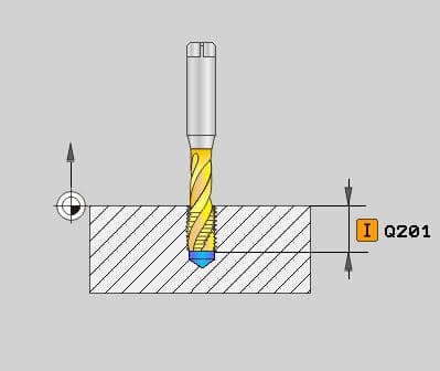
In the above cycle the tap will rapid down first to Z3. as in the G43 line. On beginning the cycle it will then rapid to what is know as the R Point. In this case R1. (one mm above the hole).
If you want to know more about G98 and G99 then read the article above.
Heidenhain Uses Cycle 207
Oh! And did You Know This??
G94 feed per minute (feed is in mm per minute).
G95 feed per rev (feed this amount every revolution)
These two G codes are your friend when you’re tapping or should I say G95 feed per rev is your friend.
Why?
When Rigid Tapping G84 Canned Cycle on a Fanuc, Haas, Mazak or similar control it is best to use G95. This means that when you programme your G84 (Tapping Cycle) your feedrate is your pitch.
The really great thing here is that if you change the speed of the tap you don’t change the feed because it’s the pitch.
Bet you have made that mistake before???
You change the speed and forgot to change the feed. We all know what happened next.
How easy is that?
Oh and don’t forget to change back to G94 at the end of the tapping.
You will notice the Heidenhain does this automatically for you.
When you don’t have rigid tapping you need a tapping head like this.
Notice how it pulls out when the tap stops and reverses.
Ok So what’s Going on Here?
Let’s tap a hole.
Start spindle forward.
Feed to depth at correct speed.
Stop spindle (tap starts pulling out).
Reverse spindle (tap pulls out a bit more).
Start spindle (Needs to reach speed).
Feed out of hole.
So the problem is that when the spindle stops, reverses and starts up everything goes wrong.
But this tension and compression tapping head can take up all the slack.
Not An Exact Science.
Definitely not, depths will vary. You will probably need to do some hand tapping too.
Tapping Clutches
These are special collets designed to slip at a certain torque. This allows you to get to depth without breaking the tap.
You adjust the collar at the front to give the required torque.
You can’t use these on Rigid Tapping G84 Canned Cycle because the last thing you want is for the tap to stop rotating.
Haas Have The Answer
Rigid Tapping G84 Canned Cycle, check out this great video on how to stop the machine half way through tapping.
Recover it without busting the tap!!
Ok So Let’s Talk About Peck Tapping
Fanuc (if you have the option) is G84.2 just programme your normal tapping cycle but replace G84 with G84.2 and add a Q value which is your pecking depth.
G84.2 G98 Z-15. Q5. R1. F1.5
Why would one want to peck tap?
Holes that clog with swarf.
Difficult materials.
To impress visitors.
Don’t Have It? Don’t Despair You Don’t Need It if You have Rigid Tapping
If you programme this.
G84 G98 Z-5. R1. F1.5
Z-10.
Z-15.
Z-20.
G80
There you have it Peck Tapping.
So you move to a position and it taps a hole 5mm deep. Because you are in a canned cycle it will repeat the procedure at Z-10. Z-15. and Z-20.