Siemens CNC Mixing MM with Inches
Category : Siemens
Siemens CNC Inches and Millimeters (Do you switch?)
CNC Training Call David: 07834 858 407

30 five star ratings on Google (Just saying)
I remember a long time ago we used to run metric programs and imperial (inch programs). So if the drawing was in inches then that’s how we programmed it. Seemed like a good idea at the time no converting figures and no need for writing on drawings.

You had an inch drawing, inch micrometer so why not have a program that’s in inches too?
One day someone (not me, honest) changed an X figure by 1 inch thinking it was a 1 mm.
The difference between one inch and 1 mm is what we call a country mile or a shit load. Anyway the part flew out the chuck on the impact of hitting the tool.
G20 was assigned to our history book. Oh and the boss shoved the broken tool up my arse.
I often work in Scotland where there are a lot of engineering companies specialising in Oil and Gas type work. As a result most of them work exclusively in inches. To be honest to me it’s a pain in the arse and I never quite get used to it. Although when I did my apprenticeship at Rolls Royce in 1971 things were just changing over so in theory I should have a brain measured in inches (it wouldn’t be many by the way).
Metrification (it’s not a new sexual identity)
I need to be careful here, because I’m now at that age where you can bang on for hours about all this kind of innocuous shit (it’s what old men do apart from pissing themselves if there’s not a toilet nearby).
If You Must
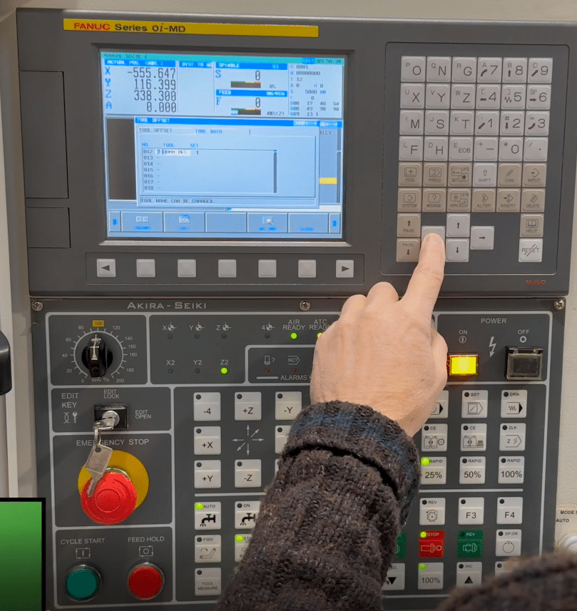
To change to inches on a Fanuc control select MDI and go to your setting screen, press the offset/settings button.
Just change from 0 to 1.


Shut your machine off and back on again then zero return it if required. Everything will change to inches (you’ll now have four decimal places)